
Triac is a semiconductor component that you can treat as a switch. Using a small signal from the microcontroller, you can control Mains voltage. However, this cannot be done directly. You need an intermediate device to be able to control the Triac and separate it from the microcontroller.
Triac is the main element of SSR. In there, all the components for control and separation are already built-in. If you want to use it yourself, you have to add it. But thanks to this, you get the most universal way to control AC Mains, and in many cases, a better solution than EMR or SSR.
Triac construction
There are opinions that Triacs are very complicated devices. No, they are not 🙂 I will try to bust this myth once and for all. In this chapter, we’ll look inside and see what the Triac is made of.
I wouldn’t like to go deep into physics. I assume that you are more interested in how to use it in a real project. Not how semiconductor structures are arranged. Nevertheless, let me at least slightly outline the topic to make this post complete.
To better explain this, let’s answer the questions: “what is …”
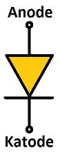
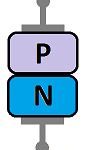
Diode
Diode is one of the simplest semiconductor devices. It passes current only in one direction.
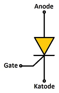
Thyristor (SCR)
Thyristor is more and less a Diode with a controlled Gate. Depending on the state of the Gate, the Diode behaves like a classic Diode or blocks the current completely.
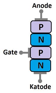
Triac
Triac is basically two thyristors connected back to back with a shared Gate. This makes it possible to control the current in both directions.
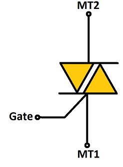
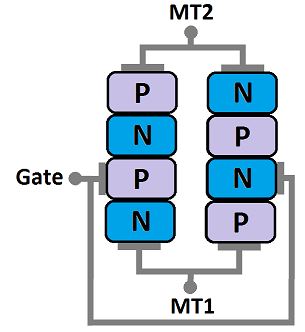
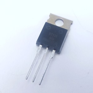
Triacs come in a wide variety of packages. All have three terminals: MT1, MT2, GATE, and a built-in heat sink.
Before screwing it anywhere, read the documentation! The radiator can be internally connected to one of the terminals. In that case, you must treat it as if it was under high voltage.
How Triac works?
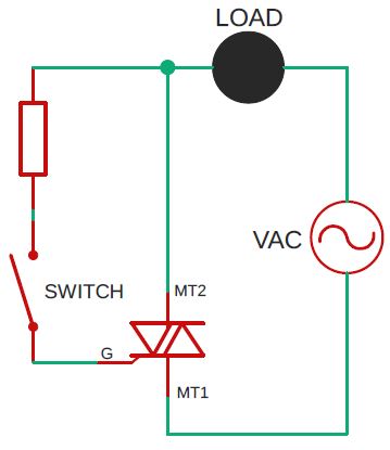
To better explain how Triac works, I have prepared this simple schematic. This is the basic circuit that allows you to control a high load current with a small “gate” current using a switch. It can be small because a very low current (mA) will flow through it.
However! Low current doesn’t mean low voltage! This switch is under high voltage! When it is closed, 230 (or 120) VAC flows through it!
Even though current can flow in both directions via the MT1 and MT2 terminals, they are not interchangeable.
To properly trigger the Triac, you must apply voltage to the Gate from the MT2 terminal. This is the one on the opposite side to which the Gate is drawn on the symbol.
Triac, like a Thyristor, has an interesting feature. It can be turned OFF only when the current flowing through the terminals drops to a value close to zero.
Two things result from this:
- Triac isn’t suitable for direct current control. In DC, the voltage and, of course, also the current never drops to zero. You can turn ON the load, but there is no way to turn it OFF.
- To trigger the Triac (classic SSR as well), all you need is a short impulse. With AC, you have to trigger it periodically, because the voltage drops to zero every 10 ms (or 8 ms).
Triac Application
I will present you two versions of the schematics depending on your needs. You can use the simple or the more sophisticated version.
Simple version of the schematic
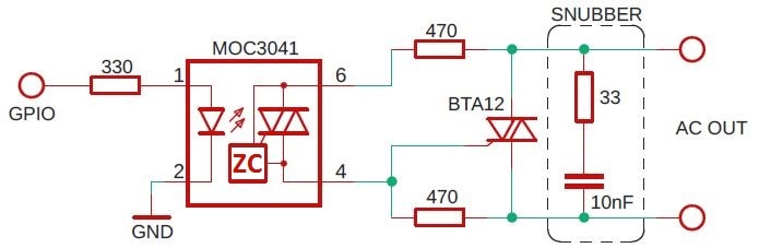
If you just want to turn ON/OFF the load circuit and don’t intend to regulate the power, then this version is enough for you.
As you will probably notice immediately, this schematic isn’t much different from the internal construction of the SSR (article about SSR). You can treat it as a DIY version of a Solid State Relay 🙂
Two things I would like to draw your attention to:
- If you use an Opto-triac with a built-in Zero Cross Detector (e.g., MOC3041), be aware that just like in the case of SSR with built-in ZCD, the switch-on delay can be up to 10 ms (at 50 Hz).
- If you want to control the inductive load (e.g., motor), add “Snubber”. This circuit suppresses a suddenly rising voltage when the Triac is turned off. In certain conditions, this may cause the Triac to turn on by itself. If you have time and want to learn more about this topic, I recommend the Application Note from ST.
More sophisticated version
Now we will only discover the most significant advantages of the Triac. Using this version of the schematic, you have full freedom in choosing the type of control (I will write more about this types in my article How to control AC voltage with microcontroller? ).
- ON / OFF Control – like in the simple version, electromagnetic Relays, and Solid State Relays.
- Phase Control
- Cycle Control
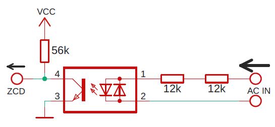
To be able to take full advantage of Triac’s capabilities, we must add one more element to our schematic: our own Zero Cross Detector. Unlike the circuit built into the Opto-Triac, this version is manual. It only gives us information about the moment in which AC Mains reaches zero voltage. What we will do with it is our business, we have complete freedom.
Zero Cross Detector
ZCD is necessary to synchronize the moment when the Triac will be turned on. In the case of ON / OFF Control and Cycle Control it will always be as close to zero as possible. In the case of Phase Control we will need to add some delay.
Some practical tips
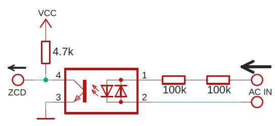
- Instead of an optocoupler with two LEDs, you can use the Graetz’s bridge to rectify the voltage. I wrote more about these two methods in article “How to detect the AC Mains voltage with microcontroller“.
- In an ideal world, the moment of switching on would always be ideally zero. Unfortunately, we don’t live in it, so there will always be some delay. It is good to minimize it, but there is no need to go crazy 🙂
How to do it?
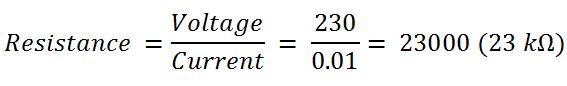
- Increasing the current at the optocoupler input will turn ON the LED faster. On the schematic is 200 kΩ, it limits the current to about 1 mA (at 230 VAC). This value is sufficient for the optocoupler to work but causes some delay. The max LED current you will find in the documentation of a specific model. For example, let’s calculate what values the resistors would have if we wanted to increase the current to 10 mA.
Of course, you won’t find a 23 kΩ resistor anywhere. In this case, choose the closest one, e.g., 24 kΩ. Or you can select two resistors and add up their resistance. The use of two resistors has another advantage: voltage and power are distributed proportionally. In my example, I will choose two 12 kΩ resistors.
Let’s calculate new values of current and power.
Don’t skip this step. If you choose the wrong resistors, they will burn!
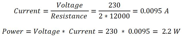
Small THT or SMD resistors usually have 0.25 W. So even using two means they have to handle at least 1.1 W each. Remember to always have a buffer. I recommend you to use two 2W resistors.
- Reducing the pull-up resistor at the optocoupler output will also result in a faster response. By reducing the current flowing into the collector, it will open earlier. Increase resistance to e.g. 50 kΩ.
- The third tip will concern the Software part. I don’t know what microcontroller you are using for this project, but it doesn’t matter. Every Arduino (ATMega), ESP, STM, PIC, Raspberry Pi will do the job. Each one can generate an external interrupt with a rising or falling edge.
Before and after changes, the chart looks as follows:
The final schematic
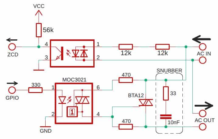
In this version, I used a different type of Optotriac. Instead of MOC3041, I used MOC3021. It has no built-in ZCD unit. I took care of it on our own, so I don’t need it 🙂 Besides, if I wanted to use phase control, it wouldn’t be possible. The rest of the schematic should be clear. Remember, MT1 and MT2 are not interchangeable!
Advantages
- No moving parts (i.e., a lifetime almost infinite).
- Much faster than Electromagnetic Relay.
- Very universal (you can choose any control method).
- No interference generated during switching (if you do it correctly).
- No sparks.
- Low power consumption in the control circuit.
- It makes no sounds.
Disadvantages
- It is never completely open (like EMR). So it has some leakage current (μA)
- Higher resistance when Triac is closed, causes it to heat up.
- Works only with AC.
- You can’t connect directly to GPIO.
- It is more complicated to use than SSR and EMR.
Triac – summary
In this article, you have learned how universal device is the Triac. By adding a few additional components to your project, you can configure it exactly according to your needs. You can use it instead of the classic relay, or you can choose a more complex control method like phase or cycle control.
Related Articles
How to program an ESP8266 – With and Without Arduino
I discovered ESP8266 a few years ago. Since then, I’m…

How to start a Smart Home – Step-by-Step illustrated guide
This is the first article in the series in which…

How to start a Smart Home – part 2
If you’re reading this it means that you want to…