

Do you think that your pet gives a shit that it’s the weekend and you need to sleep in? My cat certainly doesn’t. Every Saturday at 7 am my cat Strachu meows a serenade “I’m hungry!!”. And he doesn’t give a hoot that you went to bed late last night because: (cross out false one) you were at a party / you worked / your child didn’t let you sleep.
That is just one example where a remote feeder would come in handy.
Today I’m gonna show you how I built your own Pet Feeder and integrated it with a Smart Home. Without any further ado, let’s get down to business!
Introduction
The idea of Smart Homes is to facilitate everyday routine activities. One of them undoubtedly is pet feeding. Automatic “Smart” Pet Feeder integrated with the Smart System in your home gives many possibilities for doing it.
- You can set up a detailed meal schedule.
- You can put the food automatically after detecting a pet near the bowl. Although in this case, a lot depends on the pet itself. My Starchu would probably live by the bowl just to keep the food flowing. Yes, he is the biggest glutton on the street 🙂
- You can also just sprinkle some cat food remotely using your smartphone at any time and from anywhere.
Video version

Unique features of Pet Feeder
- Embedded presence (PIR) sensor to detect if the pet is nearby.
- Embedded beeper to inform the pet about the meal.
- Activation can take place locally or via WiFi (ESP8266).
- Separation of the electronic part for washing takes seconds, and no tools are needed. More about it in the chapter: Washing the Pet Feeder
How does it work?
At my home, the Pet Feeder works as follows:
- When the embedded PIR sensor detects that the cat near, I get a notification on my phone that it is probably hungry.
- I can decide if it’s the right time to eat. If so, I can give him some food.
- Besides, I have the option of giving him food manually. If I decide that it’s time for dinner. That’s why I put a Buzzer on the PCB. It’s gonna notify the cat that there is food in the bowl.
- I set up a schedule that dispenses a portion every day at 7 AM.
Where to get source files?
As with any other project, you can download all the source files such as schematic, PCB layout, 3D model, BOM, and config file. If you want to receive all of them, enter the email below – I’ll send a link to you straight away. If you entered your email on another project, you could use the same link that I sent you then.
Electronics
In this project, the schematic is straightforward. There’s nothing too complicated here.
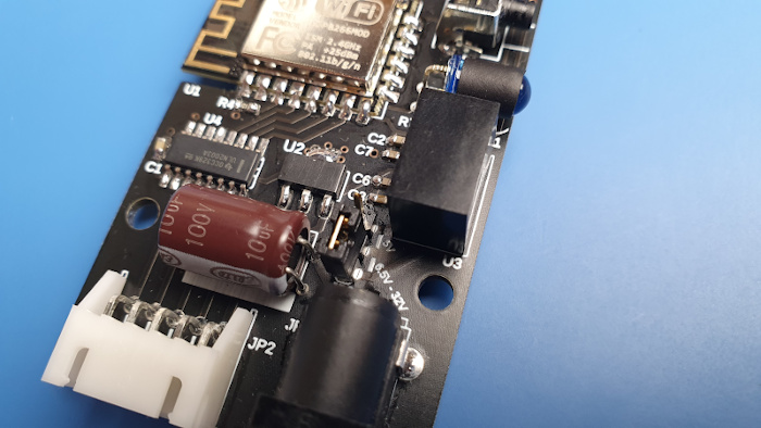
As you can see, the main brain is an ESP12F module with an ESP8266 chip on board (Aliexpress). It controls the 28BYJ-48 stepper motor (Aliexpress) via the ULN2003 (Aliexpress) driver, reads data from the PIR module (Aliexpress), supports the button, LED, and the Buzzer. And it communicates with our Smart Home via WiFi.
The Stepper Motor is powered by 5V, the rest 3.3V. That’s why I put a pulse DC-DC converter at the input, so the power range is quite broad: from 6.5 to 32V. But if you wanna power everything with 5V, this converter is redundant. Just remember to set the J3 jumper properly.


The sponsor of this project is JLCPCB. They made the board for this project. For a few bucks, and in a matter of days, you can have a professional-looking PCB in your home. And if you don’t feel up to it, they can solder all SMD components for you.
Notes for PCB assembly
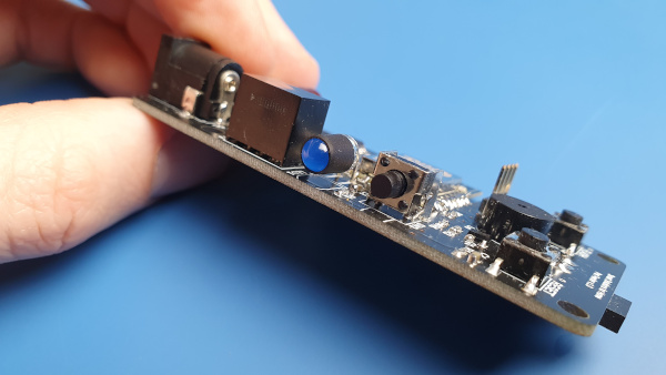
LED assembly may not be obvious. You have to bend it correctly so that it doesn’t protrude beyond the outline. Then it gonna fit perfectly into the hole in the housing (photo).
Additionally, You can cover the lens with a heat shrink tube. Thanks to this, the light doesn’t disperse that much.
The three-pin PIR module socket is the only one on the bottom side of the PCB.

If you want to power the device with a 5V power supply, you can omit the DC-DC converter. Remember to set the jumper in the right place.
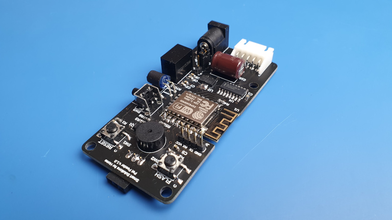
In the end, the board should look like this:

Software
In this section, I’m gonna describe the device configuration and its integration with the Home Assistant.
You gonna need a UART-USB adapter (Aliexpress) for this. You can use any adapter you can find. Generally, the cheaper it is, the better. They all work nearly the same, so it makes no sense to overpay. If you’ve done anything with the ESP chip before, you probably already have it.
I described how to program the ESP8266 chip in my other article: “How to program an ESP8266 – With and Without Arduino“.
Here, I’m gonna focus on the configuration file of ESPHome. But of course, you can use any firmware you prefer. For example, a lot of people recommend Tasmota or ESPEasy. But I personally am a fan of ESPHome. So that’s what I’m gonna focus on in this article.
Details of individual blocks of the configuration file
You can download the entire file together with the rest of the source files. That’s why I won’t describe it here to a T. I’ll tell you only about the most interesting parts.
API
The Application Programming Interface defines how the Integration in the Home Assistant gonna interact with the ESP device. If you’ve only used integrations supported natively by HA, then you probably didn’t have to do anything else with it aside from putting the command “api:”.
Unfortunately, the stepper motor isn’t natively supported (yet), but nothing prevents us from making our own API.
I added two services: to support the stepper motor and the length of the beep. Thanks to this, I can easily modify these two elements by adding in the Home Assistant additional parameter. I don’t need to modify the config to do it.
The service “start_buzzer” receives an integer variable and then passes it as a parameter of the function “delay. Thus it determines what long BEEEEP the device will do..”
The “stepper_control” service, like before, receives an integer variable, which this time will define the number of steps that the motor has to do. However, before doing so, the current position must be set to 0. Thanks to this, the required number of steps will be counted from the beginning each time.
As you can see, I’m using the command “!lambda“. It is used to inject C++ code into the YAML file. Thus, we significantly expand the capabilities of ESPHome. I’m not gonna go deep into details here. You can read more on the ESPHome website. All you need to know now is that we use this to convert a C++ variable into a language understood by ESPHome.
api:
   services:
     - service: start_buzzer
       variables:
         delay_time: int
       then:
         - switch.turn_on: buzzer_pf_id
         - delay: !lambda 'return delay_time;'
         - switch.turn_off: buzzer_pf_id
     - service: stepper_control
       variables:
         target: int
       then:
         - stepper.report_position:
             id: ss4h_pf_motor
             position: 0
         - stepper.set_target:
             id: ss4h_pf_motor
             target: !lambda 'return target;'
Stepper motor
I used the ULN2003 (Aliexpress) chip as the stepper motor driver. ESPHome supports a different, more sophisticated driver like A4988 (Aliexpress). But ULN2003 is definitely a cheaper and simpler way.
The ID must be the same as you entered when adding a new API service.
Additionally, I recommend you to set true with the sleep_when_done parameter. The motor won’t heat up or draw a current when idle.
stepper:
  - platform: uln2003
    id: ss4h_pf_motor
    pin_a: 16
    pin_b: 14
    pin_c: 12
    pin_d: 13
    max_speed: 250 steps/s

    # Optional:
    sleep_when_done: true
Switches
Important!
Due to the limited amount of pins in the ESP-12F module, I connected the Buzzer to the GPIO2. Its state must be high when connecting the power supply. Otherwise, it won’t boot. You can read more about him in the article How to program an ESP8266.
Anyway, to boot the device in normal mode (not flashing mode), you have to set GPIO2 as a switch. It’s best to do it during the first programming with the USB-UART adapter. As for the rest, you can do it later, via OTA (over the air).
switch:
  - platform: gpio
    pin: 2
    name: "Buzzer_PF"
    id: buzzer_pf_id
Binary sensors
This entire code is only for the button on the Pet Feeder. Don’t let the volume of it scare you.
All of this could be done in Home Assistance itself (not ins ESPHome), without any problem. But, in case of a WiFi or HA’s failure, I wanted to keep basic functionality working.
I assume that I don’t need to explain the basics of configuring a binary sensor. So let’s move on to more exciting lines.
The “on_release” parameter is activated when the button is, surprise, surprise: released 🙂
In this case, first, the Buzzer and LED will confirm the button pressed. Then the stepper motor will move 800 steps forward, thus dispensing portions of treats for your pet.
The “on_click” parameter is even more interesting. We can detect with it a long press of the button (min and max length). I set the detection between 1 and 5s, but you can change this time frame if you want. In this case, both LED and Buzzer will make a double flash (beep), then the Stepper Motor will retract a bit.
I did it just in case of a jam. Fortunately, I haven’t had to use it so far. But based on maaany previous prototypes of Pet Feeder, it sometimes happened that a single treat blocked the worm gear. There was no other option but to poke your finger inside to unlock the mechanism.
That’s why I added this feature now so that problems like this can be solved quickly. But as already mentioned, in this version of the device, I didn’t have to use it yet.
binary_sensor:
  - platform: gpio
    pin: 4
    name: "Button_PF"
    filters:
    - invert:
    on_click:
      - min_length: 1000ms
        max_length: 5000ms
        then:
        - switch.turn_on: buzzer_pf_id
        - switch.turn_on: led_pf_id
        - delay: 100ms
        - switch.turn_off: buzzer_pf_id
        - switch.turn_off: led_pf_id
        - delay: 50ms
        - switch.turn_on: buzzer_pf_id
        - switch.turn_on: led_pf_id
        - delay: 100ms
        - switch.turn_off: buzzer_pf_id
        - switch.turn_off: led_pf_id
        - stepper.report_position:
            id: ss4h_pf_motor
            position: 0
        - stepper.set_target:
            id: ss4h_pf_motor
            target: -200
    on_release:
      - switch.turn_on: buzzer_pf_id
      - switch.turn_on: led_pf_id
      - delay: 100ms
      - switch.turn_off: buzzer_pf_id
      - switch.turn_off: led_pf_id
      - stepper.report_position:
          id: ss4h_pf_motor
          position: 0
      - stepper.set_target:
          id: ss4h_pf_motor
          target: 800
Now you can compile the configuration file and program the ESP8266 chip. But as I mentioned at the beginning of this chapter, I wrote a separate article about it. You’ll find all the information you need there.
Before we move on to the mechanical part, it would be a good idea to test if everything works. Just connect the power supply and the stepper motor to the board. After a short while, your device gonna be online (green node in ESPHome). Now let’s move on to the second stage – Home Assistant.
Integrating Pet Feeder with Home Assistant
Integration of a pet feeder with Home Assistant isn’t as intuitive as with natively supported devices. But don’t worry, we gonna handle it.
First, we’ll create an automation referring to our custom services (stepper motor and buzzer), and then we’ll make a button (entity) on our HA dashboard that will activate it.
Finally, I’ve prepared a few suggestions on how you can use this pet feeder.
Connecting a stepper motor to Home Assistant
In the previous chapter, we prepared a configuration file for ESP8266. We also created a custom service for controlling the stepper motor. So let’s test if it works at all.
- Go to: Developer Tools -> Services

- All servicers created in ESPHome begin with the “esphome.”. Then there’s the node name followed by the service name. In my case, it is: “esphome.ss4h_pf_stepper_control”.
You also need to add a variable that will determine the number of steps of the motor. In this example, after clicking the CALL SERVICE button, the motor will rotate exactly 1500 steps.

Similarly, you can test the length of the sound the Buzzer gonna make. Just call the “esphome.ss4h_pf_start_buzzer” service and add the variable. You’ll manage without my help, for sure 🙂
Automation to handle Pet Feeder
Ok, both the stepper motor and the buzzer are working! But typing the name of the service manually every time would be extremely uncomfortable. Automation is ideal for this purpose.
- Go to: Configuration -> Automation, click ADD AUTOMATION, and then START WITH AN EMPTY AUTOMATION.
- Name it whatever you like. However, it is good when the name reflects the function of a given automation. It is easier to deal with in the future.

HINT
There is a bug in this version of Home Assistant that I am using (v. 2021.2.3). When you first name your Automation, it creates a variable that it will refer to in the future. In my case: “run_the_pet_feeder”. If you want to change this name later, Home Assistant won’t update the variable name. It’ll always refer to the original one.
Perhaps by the time you are reading this it is already fixed, but keep that in mind.
- Here we can set the time when the automation will be triggered. As you can see, my cat likes to eat breakfast at 7 AM 🙂

- In the Action section, we’re gonna call our two services. First, a short BEEP to summon the cat/dog/rabbit or whoever you have there 🙂
The second one is the rotation of the stepper motor. As you can see, it looks similar to when we tested it before.
Here you can see the most significant advantage of custom services. We could set the number of steps and the beep length directly in the ESPHome configuration file. But then any modification would’ve required the chip to be reprogramed. Now we can increase or decrease the portion of pet treats directly in the Home Assistant.

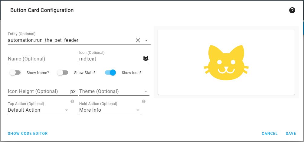
Button Card Configuration
In the previous chapter, we configured automation to be triggered every day at 7 AM. Now we gonna create a button that will let us start it at any time.
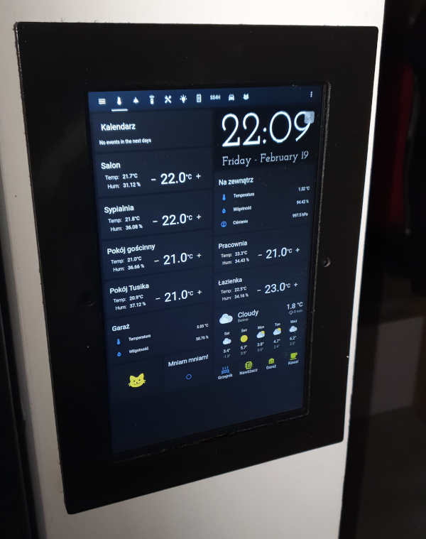
Go to: Overview, and then to the tab where you want to put the button. I’ve made a “cat-tab”, especially for this article. But I usually keep it on the main tab to make it convenient to reach.
Enter the edit mode (three dots in the upper right corner) and add a new Button Card. You can also use a Manual Card if you prefer, but that way, there will be less typing. And we like “less typing” 🙂
Although most of the configuration can be done using the visual editor, we’ll still have to switch to code editor at the end. Setting the Tap Action to Call service at here crashes visual editor..
But while you are reading this, it may already be working – check it out. If not, go to the code editor.
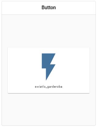
At this point, we only need to add these three lines:
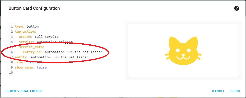
If everything went well, now you have a button that will surely be your pet’s favorite button 🙂
Embedded PIR sensor
You can use the sensor in any way you want. Even as a hidden alarm for a fridge or a drawer with candy 🙂 From the Home Assistant’s point of view, you have a human and animal detector. You can use it as a trigger for any automation. There are many possibilities, and a lot depends on your Smart system.
In this chapter, I’m going to describe three suggestions on using this PIR sensor that can inspire you.
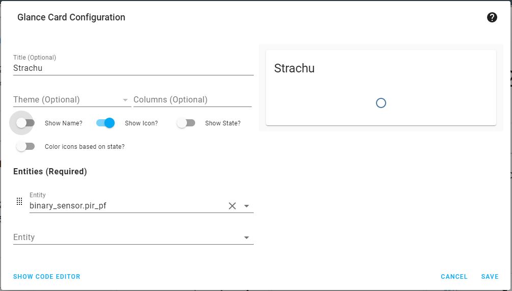
Option 1. Did the pet come to the food bowl?
You can make sure that your pet has come to the bowl and is eating food.
To do this, all you need is a Glance card. As an entity select: binary_sensor.pir_pf. Or whatever you named your PIR sensor in ESPHome.
Option 2. Starting a drinking fountain
If you have such a fountain, you can only turn it on only when the pet is nearby. You can save some money on electricity thanks to this. Or even more importantly, you can’t hear the water splashing all the time. It was driving me crazy before I did Pet Feeder.
Of course, to do this, you need to be able to turn this fountain on and off remotely. You can use a Relay Module with ESP8266 (Aliexpress) or a power socket, e.g., Sonoff socket (Aliexpress).

Option 3. “Hangry cat” – actionable notification
If you have the Home Assistant app on your phone (iOS or Android), you can receive notifications about various events. You can also decide right away if it’s a good time for lunch.
I’ve described in detail how to make such a notification on iOS and Android phones in my other article. You will find it here: Integrating Smart Doorbell with Home Assistant
Of course, in this case, a lot depends on the pet. My Strachu is hungry all the time, so I had to turn this notification off completely. But maybe yours isn’t such a gobbler 🙂

Software summary
I’m sure you’ll come up with lots of other options, suitable for your schedule. But, I gonna end this chapter now because it is too long anyway. Now let’s move on to the mechanical part of this guide.
Mechanical design

In other projects, in this kind of chapter, I described a PCB case. This time, that part of the project is the most extensive one. It took me the longest to design it, and it “cost me” a lot of unsuccessful prototypes. But that’s the only way when reliability is a key feature.
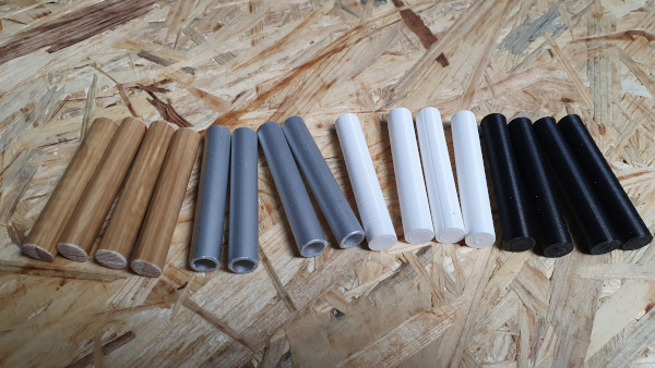
Various variants
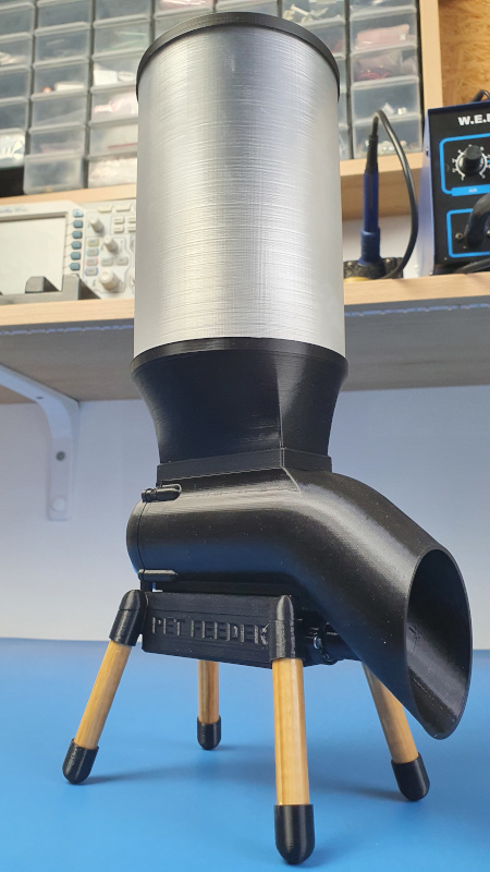
The housing has several variants. You can match it to the interior of the room in which it is located. In my case, the Pet Feeder is placed in a black and wooden kitchen. That’s why this is what my version of the device will be like.
Yours can have a body with wooden legs, galaxy black body with aluminum legs, be all white, or whatever combination you want 🙂


Assembly
Ok, you have all the parts printed (it takes about 18 hours, so congratulations on your persistence 🙂 ). It’s time to put them together. Apart from the printed elements themselves, you’re gonna need a few M2.5 and M3 screws, a screwdriver, and cyanoacrylate glue (Superglue).
Step 1
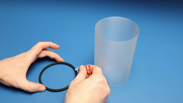
Let’s start with the food container. You can print it with transparent filament or use a plastic Coca-Cola bottle (1.75 l). If it’s available in such a bottle in your country.
If you use a bottle, you gotta start by drinking it 🙂 Then tear off the label and cut it to a height of about 20 cm. Thanks to this, you can save some time with the 3D printer. Besides, the container will be much more translucent than the printed one.


The next steps are identical for both versions.
First, we gonna mount the flap frame on the top edge of the container. Just put some glue in the groove and slide it over.


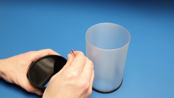
Step 2
Do the same on the other side, but glue the funnel this time.
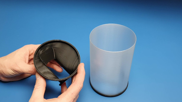


Step 3
Place the worm gear into the main body, and then insert the funnel with the container into the slot.

Step 4
Place the Lid on and fasten it with four M2.5/10mm screws.


Step 5
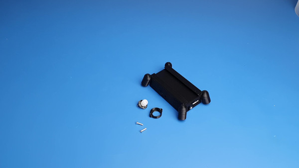
Now we’re gonna make the PCB box, which is also the base of the device.
The box consists of three parts: top, middle, and bottom. I designed it this way so it could be printed without supports.

Use M3/6mm screws to assemble the top and middle parts of the PCB box. The best way is to use Inserted Nuts (Aliexpress). Thanks to this, it will look professional 🙂 But if you want, you can glue these two parts together with cyanoacrylate glue. It should be ok too.


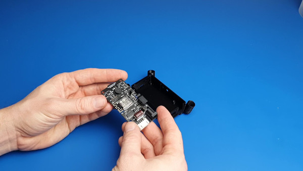
Step 6
You’re gonna need four M3/6mm screws to attach the PCB. After that, make sure you can press the SW3 switch, and the LED1 is in the right place.
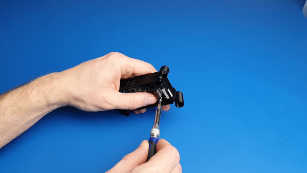
Step 7
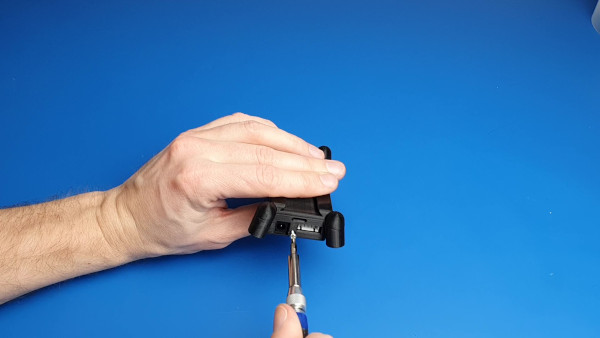
Use an M2.5/10mm screw to close the PCB box with the bottom part. Screw it down very gently. There’s not much plastic in there, so you can easily break it.
Step 8
The PIR sensor (Aliexpress) has to be installed at some distance from the PCB box. That’s why I designed a PIR spacer. Tighten both elements with M2.5/10 mm screws.


Step 9 (optional)
The PIR sensor has a white lens by default. While that’s ok with the white Pet Feeder, it looks odd with the black one. If you want, you can replace it with a black lens (Aliexpress).


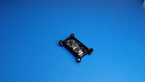
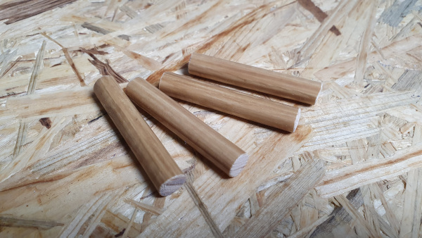
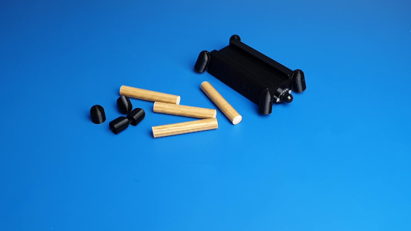
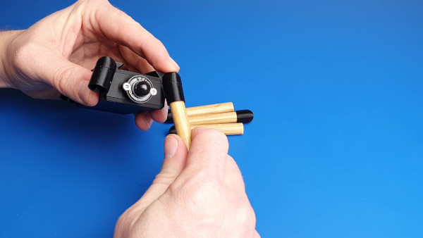
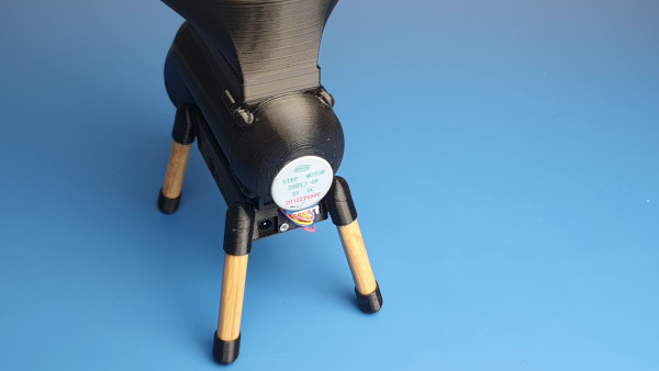
Step 10
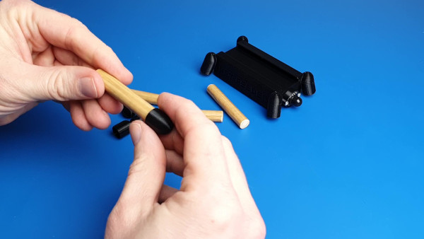
The legs can be made of wood, aluminum, 3D printed, or anything else. The diameter of this should be 10 mm, and the length depends on the high of your pet’s bowl. In my case, 60 mm is the perfect length.
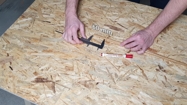

How silly it would sound, put a foot on a leg 🙂 Then attach it to the PCB box. Depending on your printer’s tolerance and the leg itself, you may need to use some glue to make sure they don’t fall out.
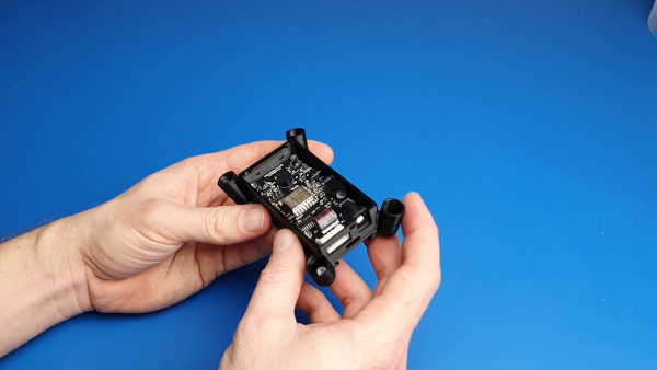
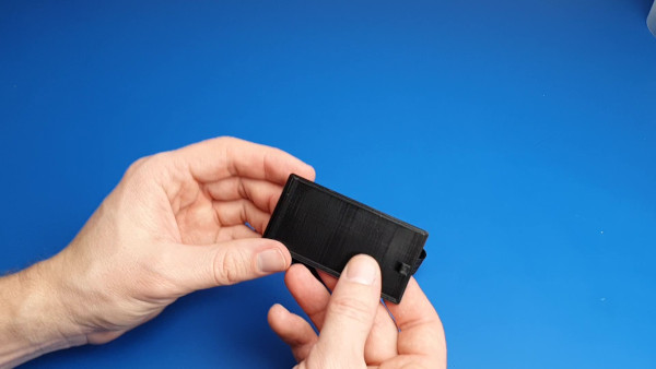
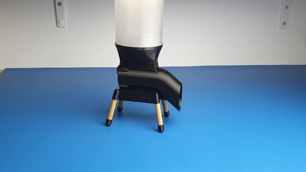
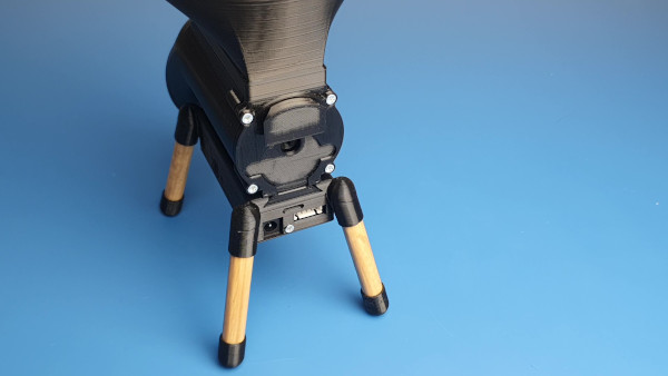
Step 11
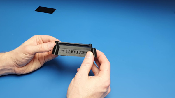
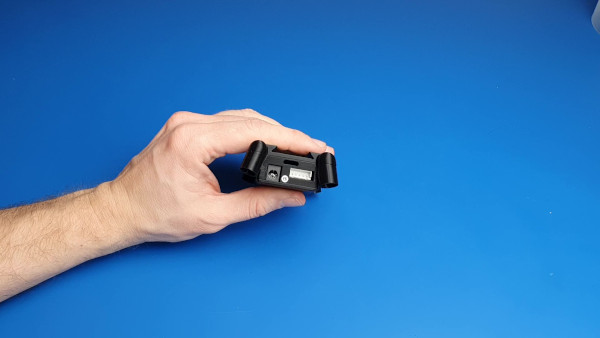
Slide the body into the groove of the top of the PCB box. Make sure the PIR sensor is in front.


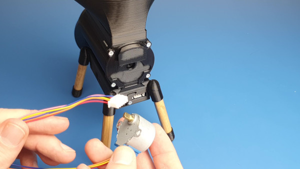
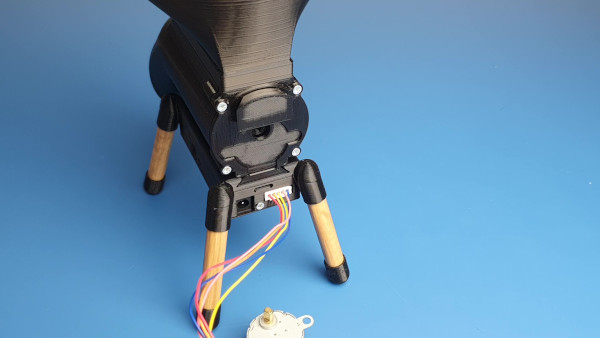
Step 12
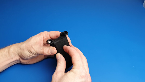
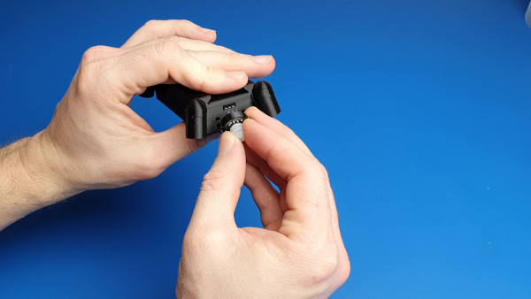
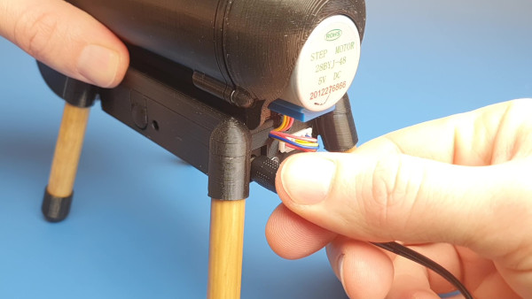
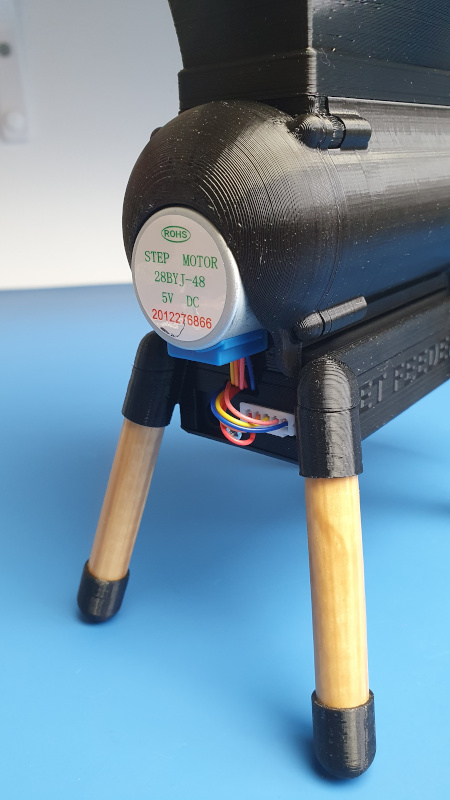
To install the stepper motor (Aliexpress):
- Connect the plug to the socket.
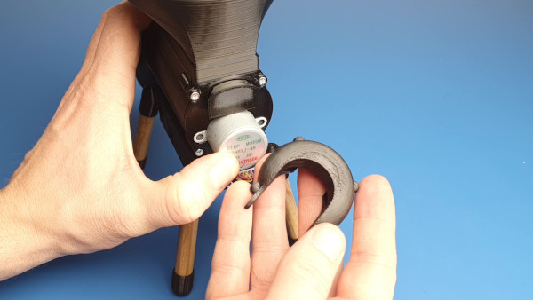
- Hide the excess cable in a hole on the back of the PCB box.
- Put the motor in the slot, and slide the motor cover down. Which also serves as a PCB box lock. This will keep the Pet Feeder in one piece. And it will allow for quick disassembly if needed. I gonna write more about it in the next chapter.


Step 13
There isn’t much to write about 🙂 Just connect the power plug.

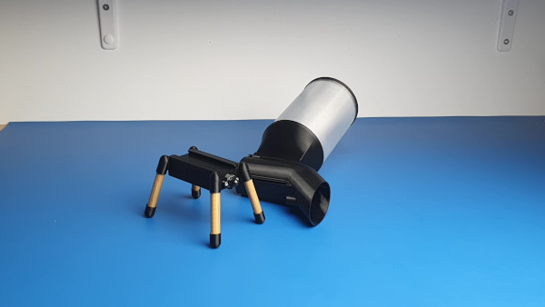
Step 14
And now the cherry on top. Close the container with the flap, and you’re done. Congratulations! 🙂


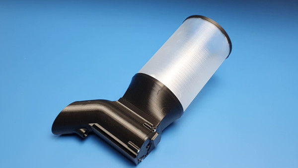
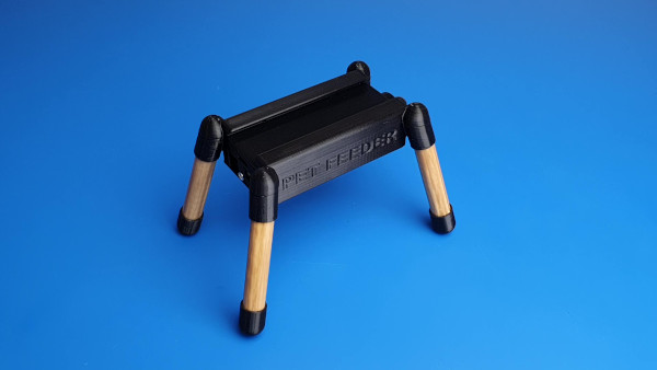
Assembly summary
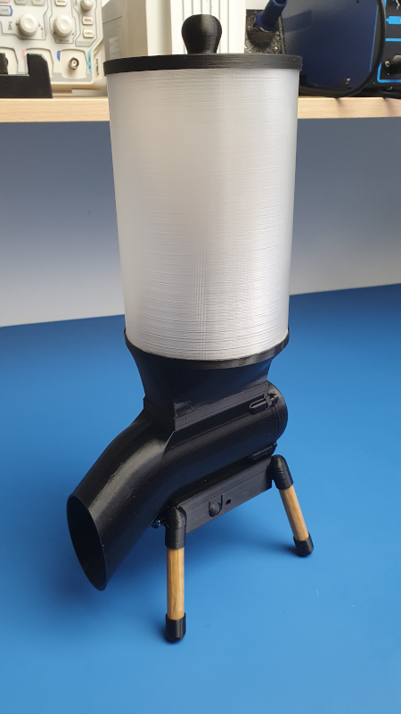
Your Pet Feeder is ready! It looks fantastic, isn’t it? 🙂
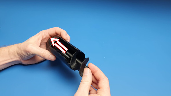
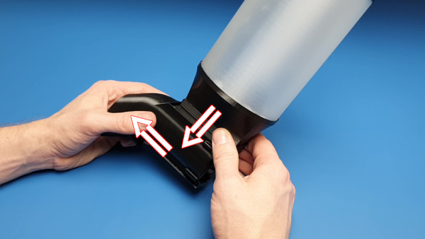
Washing the Pet Feeder
Because it is a food-related device, it would be appropriate to wash it once in a while. That’s why this project took me sooo much time. I wanted to be able to separate the electronic part from the “food” part in a matter of seconds and without any tools. And I think I managed to achieve it.
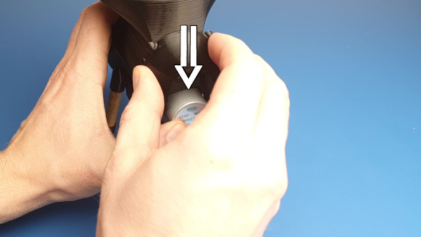
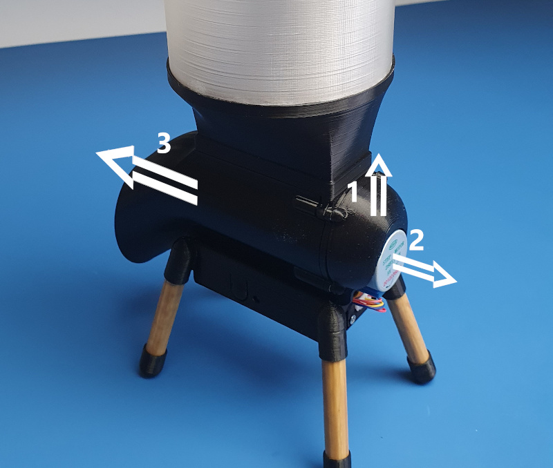
All you need is three steps:
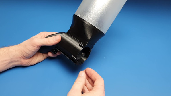
- Slide the stepper motor cover upwards.
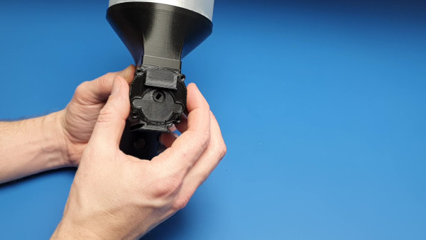
- Pull out the stepper motor.
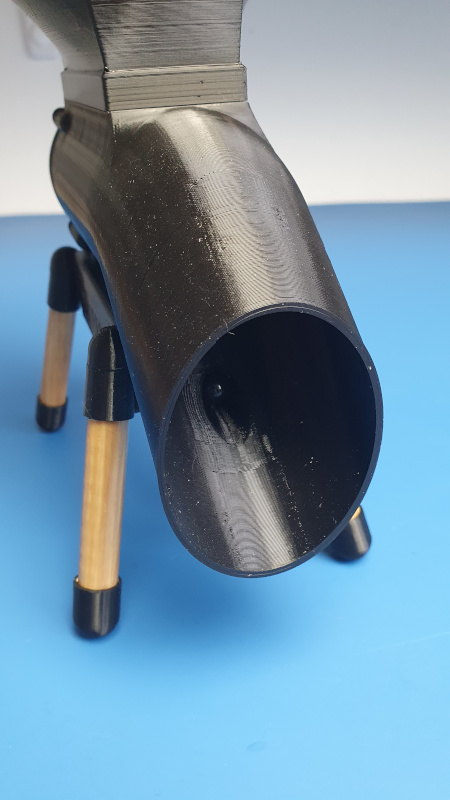
- Pull the entire body of the device forward.
This way, you can safely wash the inside of the device without the fear of getting the electronics wet.
Summary
Thanks for sticking to the end!
At the time of writing this article, I have been using SS4H-PF Pet Feeder for two weeks. And there have been no problems with it yet and I hope it’ll stay that way. If something changes, I’ll come back and make an update 🙂
If you have any questions or suggestions, feel free to contact me at contact@smartsolutions4home.com
Related Articles

SS4H-ZRG Zigbee Rain Gauge – DIY project based Zigbee Door Sensor
In this article, I’m going to show you how to…

SS4H-SSR Smart Extension Board – DIY project based on ESP8266
With these kinds of projects, they are often created when…

SS4H-SHH Smart Home Hub based on ESP32 POE
Personally, I’m a fan of centralized “smart” systems. Thanks to…