

If you’re tired of standing behind a garden hose, you’ve probably already been interested in automatic irrigation systems.
There are many commercial controllers on the market. Usually, every sprinkler manufacturer offers one. However, they have a big disadvantage. You must have a dedicated application on your smartphone to control them. And integration with an open “smart” system, like Home Assistant, is difficult or impossible.
That’s why I decided to design my device. And in this article, I’ll show you how to build it!
Introduction
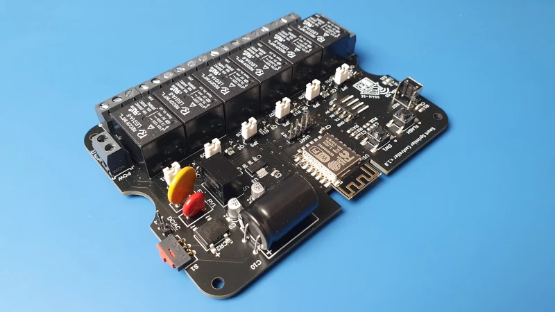
The SS4H-RC is a six-channel irrigation system controller. So it can control up to six sections of sprinklers. It has WiFi based on the classic ESP8266 chip (Aliexpress), so integration with any “smart” system is very simple. I use Home Assistant, so I’m gonna use it as an example to tell you how you can do it with the ESPHome.
Features / functions of the controller:
- I’ve already mentioned wifi.
- Two inputs for wired sensors for rain, humidity or anything else. One is analog and the other is digital.
- Touch display – Nextion 2.8 “, on which you can design any GUI (the Graphical User Interface). For me It is a local interface to control the system, and when idle, it displays the time, temperature, humidity and outside pressure.
- It can be powered by AC or DC in the range from 6 to 32V. It’s best to use the voltage the valves require. Then, without unnecessary cables and complications, everything will be powered by one cable. Most valves require 24AVC so you’re gonna probably be using this voltage.
- Protection against sudden voltage surges at the power input.
I designed this device with an irrigation system in mind. However, it’s so versatile that it can also serve other purposes. You can use it to turn off any device.
Video version

Source files
You can download all the source files such as Schematic, PCB layout, 3D model, BOM, and Firmware. If you want to receive all of them put the email below – I’ll send a link to you straight away.
Where can I buy it?
On the other hand, if you don’t want to do it yourself, you can visit my store 🙂
Electronics
When you download the schematic, you’re gonna see that it isn’t very complicated. Therefore, I’m not gonna dwell on each element separately. I’ll describe groups of elements.
Power Supply

This is the power connector. You can use AC or DC in the range of 6 to 32V.
If you are using AC, the order of the wires connected to the connector doesn’t matter. If you are using DC, theoretically the order doesn’t matter either. However, if you want to bypass the rectifier and thus the voltage drop on the diodes, put the jumper JP7. In that case, polarization is crucial.
In addition, as a protection, I’ve placed a fuse and a varistor. If for some reason a spike of voltage appears at the input, the varistor will short-circuit and the fuse will disconnect the power.
Then there is a DC-DC converter that will lower the voltage to 5V. This is exactly what LCD and relays need.
And finally, there’s an LDO (Aliexpress) that reduces the voltage to 3.3V to power the ESP8266.
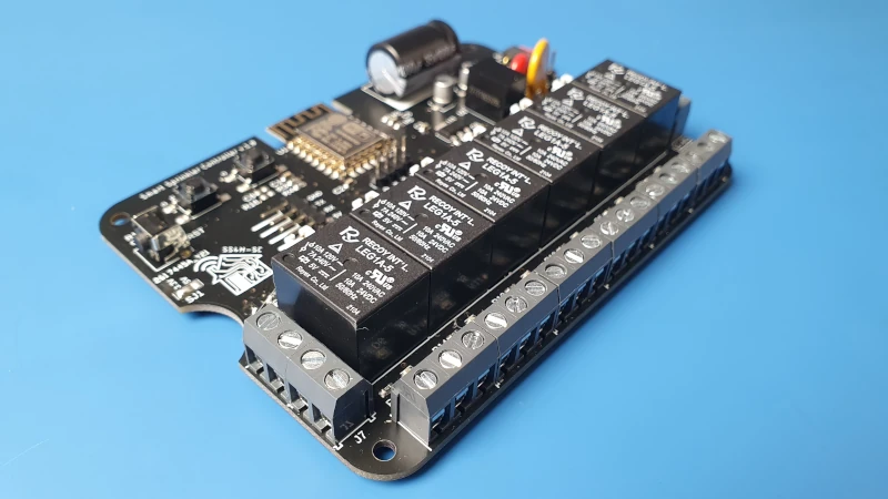
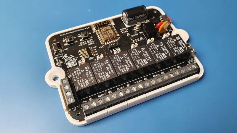
The Relays
Three outputs of the terminal are assigned to each of the 6 relays. Two of them are fully insulated NO contacts. You can even use them to switch mains voltage if you want. However, if you put the jumper JPx (where x is the number of the relay) on, one of the outputs will be connected to the supply voltage (most likely 24VAC). Thanks to this, you don’t have to make additional bridges between the connectors to pass the power.
The third output is connected to the second pole of the power supply. If you’re using AC it’s Neutral or Phase. If you’re using DC it’s GND.

Sensors
Connectors J8 and J7 are inputs for wired humidity, rain, or whatever sensor. One of them is analog and the other is digital. Plus VCC and GND. The VCC can be 3.3V or 5V. Just shorten the appropriate pads on the SJ1.
If you want to use an analog sensor, you must be sure that the maximum voltage doesn’t exceed 3.3V. That’s why I put a resistor R18 on the schematic. Thanks to which you can make a voltage divider suited to your sensor. The 10k value is just an example, don’t mind it.
The digital input is shortened with the SW1 switch. Unfortunately, there is no free pin available in the ESP module. So you can use this button or external digital input. Fortunately, there is a display where you can make as many virtual buttons as you want.

I designed it this way in case you want to use this controller without the display. Then a mechanical button could be handy.
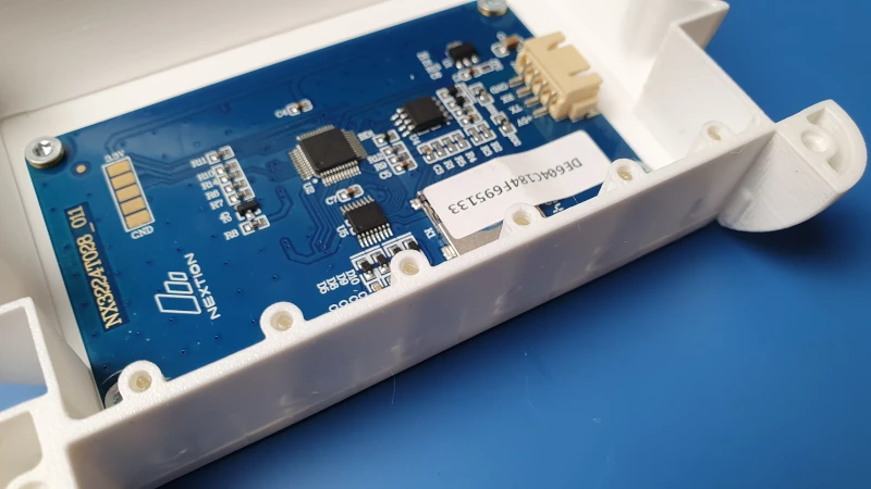
The Display,
The connector for Nextion Display is named DISP. The display on its board has an STM32, which generates graphics. This makes the LOW-END ESP8266 sufficient. Otherwise, we would need at least ESP32.
Chip is connected to the display via the same UART that is used for programming. And that’s why programming has to be done in two independent steps. But as I mentioned, this controller can function successfully without a display. If you’d like to install it in some hard-to-reach place, maybe there is no need to have a local interface?
The final result
Software
Due to the fact that the display has its own microcontroller and the device has its own, we have to program it independently. In both cases, we can use the same UART-USB adapter. However, for the display, we can use a microSD card as well. And I recommend this method because it’s much faster.
Nextion Display Programming

You can use the Nextion Editor software to create a nice GUI. This is made by the manufacturer and you can download it absolutely free from their site: LINK I’m not gonna do a full tutorial on how to make a GUI in this article. This deserves a completely separate long article and not just one small chapter 🙂
The internet is full of interesting descriptions of how to get started. It’s really simple, in just a few moments you’ll learn everything you need to create a nice graphical interface.
ESP8266 programming
I wrote a separate article about programming ESP8266: LINK.
ESPHome natively supports Nextion displays. So, all you have to do to establish communication with the display is: configure the UART and add the component: Nextion.
uart:
  rx_pin: 3
  tx_pin: 1
  baud_rate: 9600

display:
  - platform: nextion
Now, from the ESPHome, we can see all the entities we created in Nextion Editor. For example, a button on the display with ID 1 is seen here as a classic binary sensor. And in this case, pressing it will turn on the first relay. As you can see, I turn on (or off) the relay locally. And just inform the Home Assistant that the SWITCH has changed its state. Of course, you could send information via WIFI to the Home Assistant that button on the display has been pressed, and then, in response, get information which relay should be turned on. But in case of WIFI problems, it wouldn’t be possible to turn on (or off) the relay. Which is IMO the whole point of having a local interface.
binary_sensor:
  - platform: nextion
    page_id: 0
    component_id: 1
    name: "bt1"
    id: bt1_id
    on_press:
      then:
        - switch.turn_on: relay_1
    on_release:
      then:
        - switch.turn_off: relay_1
Additionally, each Relay is a “switch”, so nothing stands in the way of toggling it remotely. So you can make any schedule or automation you want.
switch:
  - platform: gpio
    pin: 16
    name: "Relay 1"
    id: relay_1
Of course, you’ll find the entire configuration file for ESPHome in the files I shared with you.
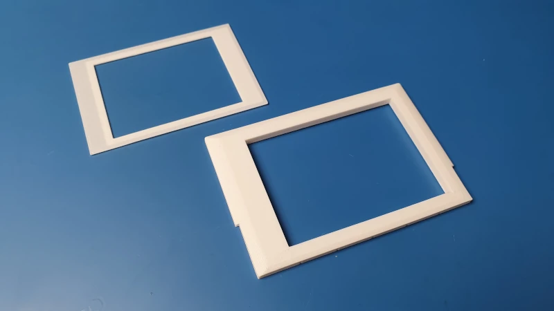
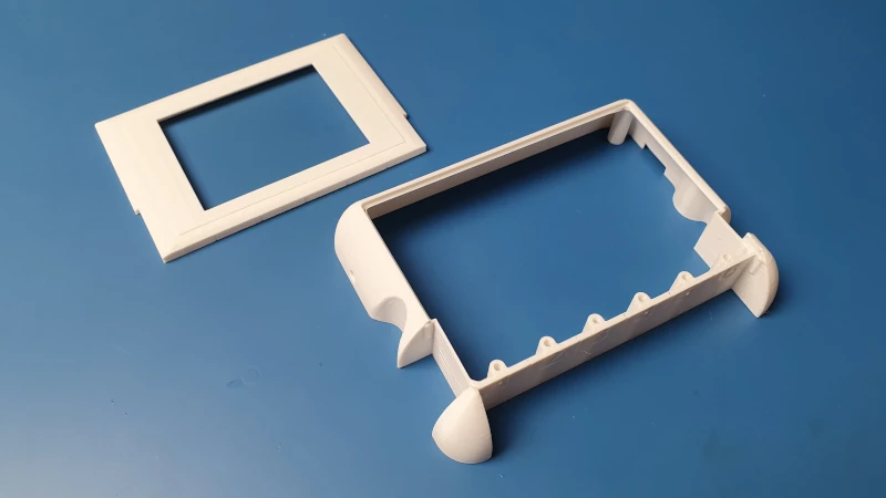
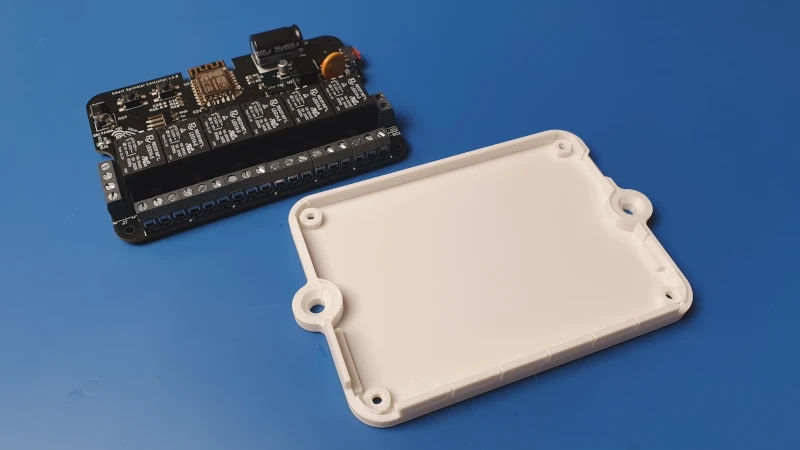
Case
I designed the housing so that it can be printed completely without supports, however, its shape is so complicated that it forced me to divide it into several smaller pieces. Therefore, now you will have to stick them together
Assembly
Before we start. In the following instruction, I’m gonna use the names of the elements that are in the package of files that you’ve probably downloaded.
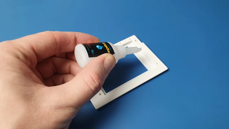
Step 1
Glue the LCD Holder and LCD Masc together.
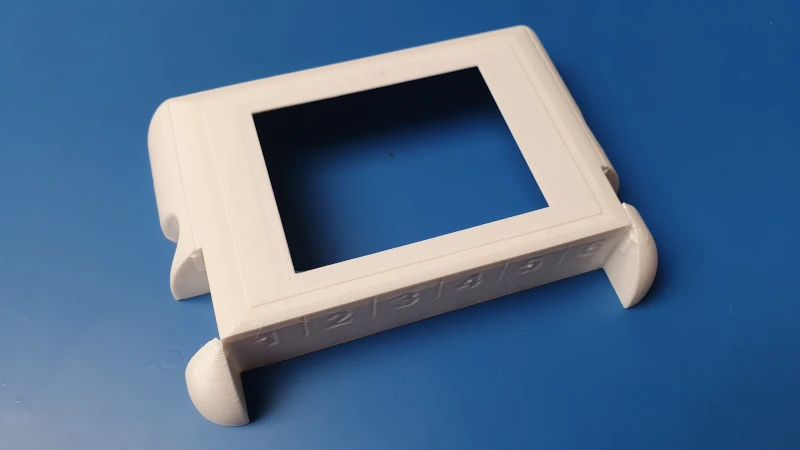
Step 2
Glue the Case Top and the assembled part from the first step.
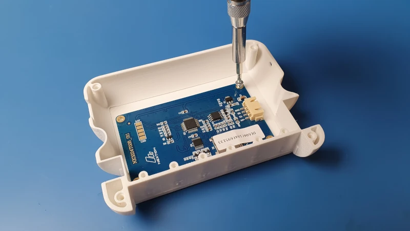
Step 3
Screw on the Nextion Display (Aliexpress) with M3x3 mm screws.

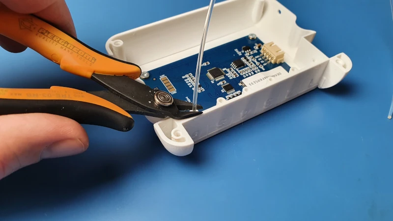
Step 4
Insert the 1.75 mm transparent filament into the special holes. The type of filament doesn’t matter. Then pull it out by about 1 mm and cut it with pliers. This is roughly the height of the soldered LED. This acts as an optical fiber. Thanks to this, we get a nice effect of the indicator of whether the Relay is turned.
Step 5
Insert the assembled PCB with Case Bottom.
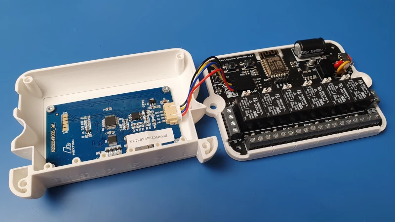
Step 6
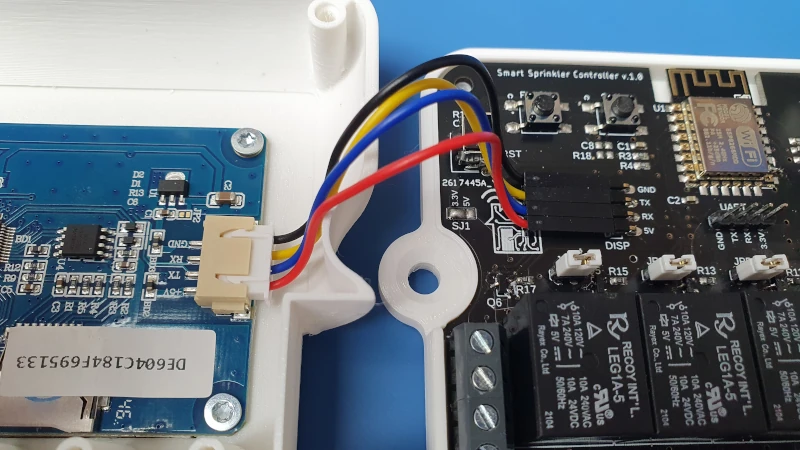
Connect LCD with DISP connector on the Sprinkler Controller’s PCB. Make sure the order is correct: 5V -> 5V, GND -> GND, RX -> TX, TX -> RX.
Step 6
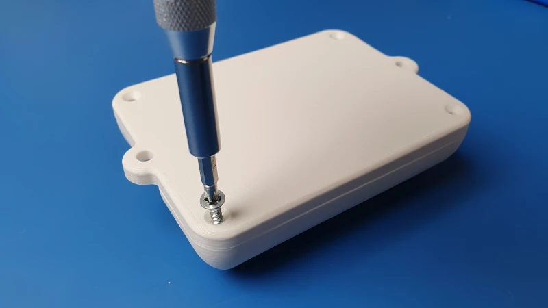
Screw on the Case Top and Case Bottom with 3x10mm wood screws.

Step 7
Do this step after mounting the Controller to the wall. There are special mounting holes for it on both sides of the case. I didn’t make a separate step for it because how you should do it depends very much on the type of wall you have.
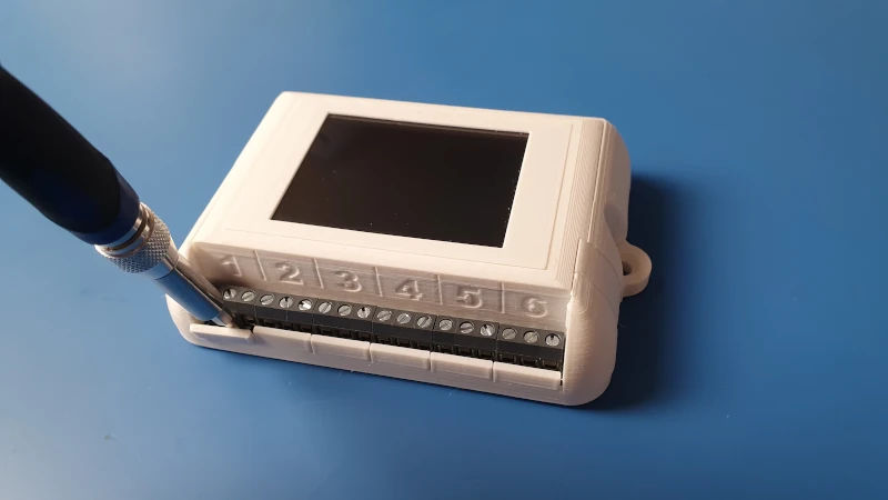
Now you can break the locks as many sections as you have. And after tightening the wires, put on Terminal Cover A, B, and C.

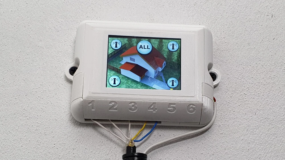
In the end, the finished device looks like this:
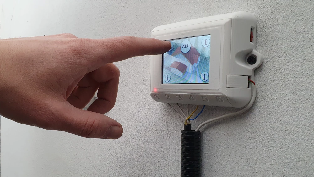
Summary
Thanks for sticking to the end!
The fully functional controller should already hang on your wall. You can now activate your sprinklers remotely or locally. Additionally, the interface can display any information from the Home Assistant in the meantime. If it’s in the garage you can use it to activate the alarm or turn off all lights when you are leaving the house. The possibilities are endless 🙂
If you have any questions or suggestions, feel free to contact me at contact@smartsolutions4home.com
Related Articles

SS4H-ZRG Zigbee Rain Gauge – DIY project based Zigbee Door Sensor
In this article, I’m going to show you how to…

SS4H-SSR Smart Extension Board – DIY project based on ESP8266
With these kinds of projects, they are often created when…

SS4H-SHH Smart Home Hub based on ESP32 POE
Personally, I’m a fan of centralized “smart” systems. Thanks to…