
A SSR (Solid State Relay) is a semiconductor switch. Using a small signal, e.g. from a microcontroller, you can control a large load. Both circuits are galvanically isolated, which simplifies the control very much. It has no moving parts, which affects the long lifetime and high reliability. The disadvantage of SSR is the relatively small maximum current that can handle.
SSR construction
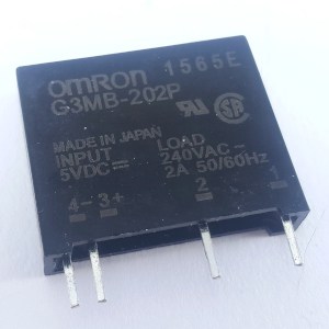
Let’s look inside the SSR. As an example I will use the popular model G3MB-202P.
The general block diagram is as follows:
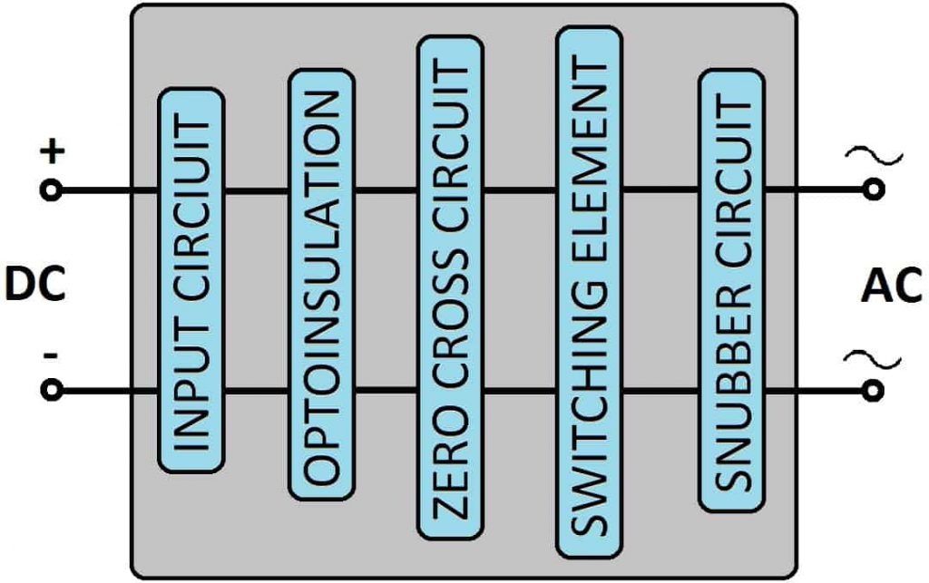

It is a circuit, and it can be connected directly to the microcontroller. It is galvanically isolated from a high power circuit.
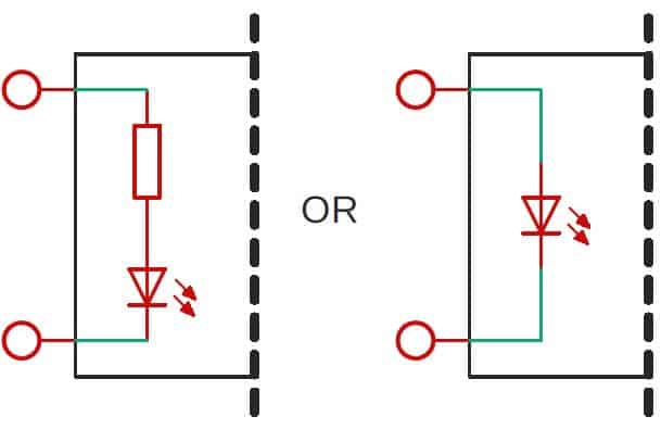
It can be LED itself or LED and resistor. In the first case, check the “LED forward current” value in the documentation. You must choose the appropriate resistor value yourself, using this formula:
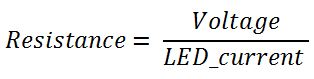
Example: If the supply voltage is 3.3 V and the required LED current is 10 mA, resistance should be 330Ω.
In the second case, when the resistor is already built-in, you can connect the pin directly.

For SSR adapted to AC voltage, the optocoupler will most likely be an Opto-Triac. In the case of SSR for DC voltage, it can be an optocoupler with a transistor output.
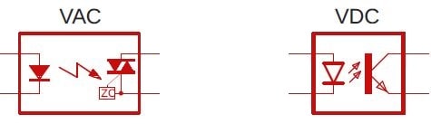

You can find SSR with or without Zero Cross Detector (what is ZCD I wrote in this article in the chapter about noise generating). It depends on how you want to control the load circuit. If you’re going to use “phase control”, you must choose the version without ZCD.
The Zero Cross circuit itself is usually built into the Optotriac. In the picture above, you can see the “ZC” badge. It means that the Zero Cross circuit is embedded.

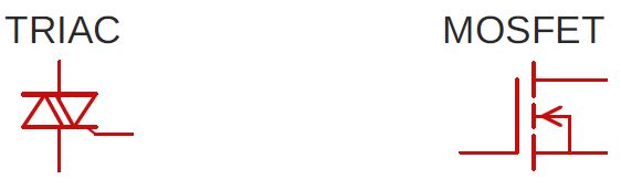
It is the main actuator. In the case of alternating current version, it will be a Triac (entire article about Triac) or Thyristor. In the case of the direct current version, it will be most likely a MOSFET.

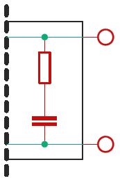
When switching OFF inductive loads, e.g., motors, a sudden voltage increase may occur, and that can cause faulty ignition of the Triac. This is what the Snubber Circuit is for. Its task is to absorb that sudden voltage surges. It consists of a capacitor and a resistor connected in parallel it SSR outputs.
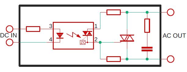
To sum up the description of the Solid State Relay construction, I drew a schematic that collects all the elements described earlier.
How SSR works?
From the outside point of view, it is straightforward. Powering the control circuit will close or open the load circuit. Same as Electromagnetic Relay (you can find the EMR article here.).
It is more interesting from an internal point of view:
- powering input terminals turns ON the LED in Opto-Triac,
- it activates the “small” Triac,
- which enables the “big” Triac,
- which is physically responsible for closing and opening the load circuit.
Note.
In the article about Triac itself, I tell you how to design your SSR – DIY style. There will also be more details about how Triac works.
Types of SSRs
There are several types of SSRs. Due to the kind of galvanic isolation, we can distinguish:
- opto-coupled
- transformer-coupled
- reed-relay-coupled
Due to the type of load voltage:
- VAC
- VDC
Of course, there are subtypes in each category. For example, the actuator in the case of VAC Relay may be the Triac or Thyristor. As you can see, there are many types, I could write the whole article just about it, but I think that this is pointless.
The most important thing you should pay attention to when choosing SSR for your project is the maximum current and type of load voltage.
Advantages of SSR
- No moving parts (i.e., a lifetime almost infinite).
- Galvanic isolation.
- Much faster than EMR.
- You can connect directly to GPIO (if the voltage is right).
- No interference generated during switching.
- No sparks.
- Low power consumption in the control circuit.
- Built-in ZCD circuit (optional).
- It makes no sounds.
Disadvantages of SSR
- It is never completely open (like EMR). So it has some leakage current (μA)
- Higher resistance when SSR is closed, causes it to heat up.
- Works only with AC or DC (never both).
SSR Applications
Solid State Relay is very simple to use. You can treat it as a regular Relay. But it’s even simpler because there is no inductance at the input. So you don’t have to worry about voltage pins when turning the power off.
If the voltage levels match, then you can connect the SSR directly to the microcontroller. However, if it needs more voltage than available on GPIO, you can use a transistor. Just like I did with Electromagnetic Relay.
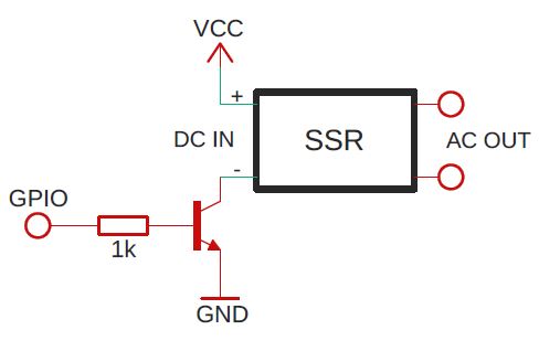
If your SSR doesn’t have a built-in resistor, remember to add it. Otherwise, you will burn the LED. But besides it, as you can see the schematic is straightforward and easy to understand 🙂
Below is a graph showing the moment of switching on the relay. The BLUE chart is a control circuit, and YELLOW is its load.
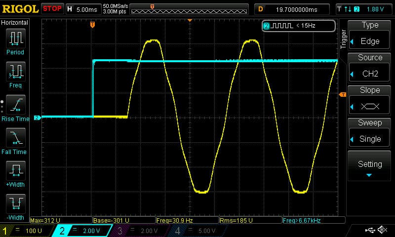
In the advantages, I wrote that SSR is fast, but what does the graph show?? 7 ms delay?? How is this possible??
This model has a Zero Cross Detection unit. That is why it can be turned on only when the AC Mains voltage is (near) zero. So delay can be extended up to 10 ms in the EU (or 8 ms in the US). Keep this in mind when designing your device. But thanks to this, you can avoid interference that is generated during switching. If you need the SSR to switch on immediately, e.g., for phase control, use a model without ZCD.
Solid State Relay – summary
SSRs are becoming more and more popular. It won’t get EMR out of the market soon, but they will take a large part of it.
Their most significant advantage is reliable work for many years, no interference generation (ZCD), and simplicity of use.
The disadvantages are undoubtedly the leakage current – when it is “open”, and heating when it is “closed”.
Related Articles

How to program STM32 – The Complete Guide
In this article, I’m gonna show you how to program…

What is Smart Home?
I’ve been dealing with Smart Home for a couple of…

How Hybrid Relay works? – The Complete Illustrated Guide
The Hybrid Relay is a combination of electro-mechanical and semiconductor…