
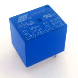
The Relay (EMR or Electromagnetic Relay) is an electro-mechanical component that uses a magnetic field to close and open the circuit. The most crucial element is the coil. If current flows through it, it turns into an electromagnet, which attracts contacts that close or open the load circuit.
Relay construction
Relays can have many different shapes, sizes, numbers of terminals, coil voltage, and maximum load current. However, the basis of construction is the same. We can divide it into two circuits. There is a control circuit that consists of a coil that generates magnetic fields. And there is a load circuit that has movable armature, spring, yoke, and contact switches. Everything is enclosed in a plastic housing. Only the thermals stick out.
I broke one of my relay to show you how it looks inside 🙂

How Relay works?
The way the Electromagnetic Relay works is relatively simple and intuitive. It uses the magnetic field created by the coil to attract contacts that close or open the circuit. The mechanical contacts are physically touching and allow electricity to pass through.
It is a binary device, i.e., it has two states in which it can be. Let’s follow these states.
I drew two pseudo schematics to illustrate how it works. In the real project, you will have to modify this schematic a bit. But more about that in a moment. Let’s focus on how the relay works. For the sake of simplicity instead of a microcontroller, there is a switch that closes and opens the circuit.
State 1: control circuit not powered

When the coil (control) circuit is open, no magnetic field is generated. The switch is in the NC (normally closed) position. The load circuit is open, so the light is off.
State 2: control circuit powered

In this case, it’s exactly the opposite. A powered coil creates an electromagnetic field that attracts the contact switch and thus closes the load circuit. The light is on.
This is what the relay looks like during switching.
Common Types of Relay
The most popular types you’ll be dealing with are:

- SPST (Single Pole Singel Throw)

- SPDT (Single Pole Double Throw)

- DPST (Double Pole Single Throw)
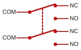
- DPDT (Double Pole Double Throw)
Relay Applications
Using a relay in a project is really simple. However, there is a coil at the input, i.e., high inductance. When you disconnect the circuit, the coil will cause a large voltage pin. It may damage the GPIO, so I don’t recommend to connect it directly to the microcontroller.
This is what it looks like when the power is turned off.
Now imagine what would happen if the relay was controlled directly from the GPIO. I’m afraid even to imagine 🙂 So I will quickly show you what to do to avoid such a pin.
Parallel to the coil, add a diode (preferably a fast one, e.g., Schottky). Polarization of diode is crucial: Anode to GND and Cathode to VCC (see schematic below).

Now the graph should look much better.

Two more problems left: voltage difference and power consumption.
If the coil requires a higher voltage than the microcontroller can give, it is necessary to adjust these levels. Usually, you’ll want to connect a 5V or 12V Relay to uC, which operates on 3.3V. But even when the voltage levels match, I still don’t recommend to plug it directly to the GPIO. There is also the issue of high power consumption. The coil can draw up to 100 mA, which is far too much for most microcontrollers. Fortunately, there is a straightforward solution: a Transistor.
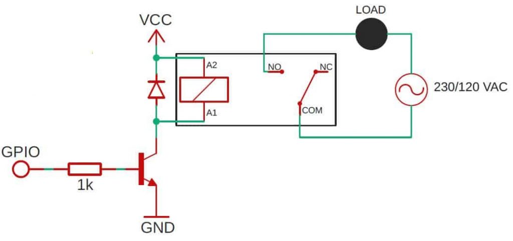
You can treat the above schematic as the final one. I used an NPN transistor here, but if you want, you can use another kind.
What you need to pay attention to is that the VCC on the schematic refers to the coil voltage (e.g., 12 V).
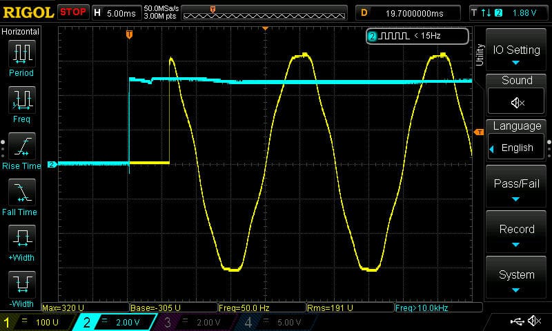
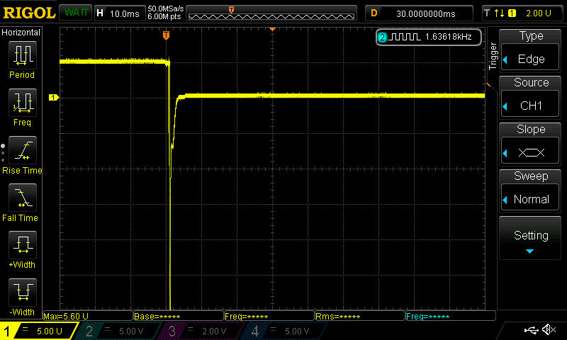
As you can see, the delay between powering the coil and closing the contacts is about 6 – 7 ms. This value may be slightly different for different relay models. But there will always be a delay.
You can see something else in the graph above. When the contacts were closed, the AC Mains was over 300 V! Such sudden voltage surges cause a lot of noise. Also, the higher the load, the worse the interference.
If you use a Relay, e.g., to turn on the light, by default, switching will occur rarely. So you don’t have to worry about it. It would be different if you wanted to control the motor speed and would like to “click” every few dozen ms. Don’t do that 🙂
HINT:
If you add a Zero Cross Detection circuit to your project, you can try to get closer to zero. Of course, you don’t hit perfectly at “zero”. But even if you get closer to it, you can increase the lifetime of the relay ten times.
Advantages
- You can use it for high currents and voltages – 20 A or even more.
- The coil is galvanically isolated from contacts.
- They are cheap.
- Voltage drop on contact terminals is small because their resistance is minimal (milliohms).
- You don’t need a heat sink at all.
- You can use it for AC and DC.
Disadvantages
- Durability (the number of switches) is limited.
- They work with quite a delay (a few milliseconds).
- The coil can draw up to 100 mA.
- You can hear the “click” when switching.
- They make electrical noise.
- Produce sparks on switching.
Electromagnetic Relay – summary
You can use EMR to turn the light ON and OFF, to control roller shutters, for fans, and many other things. I’m sure you have plenty of ideas on how to use them in your project/s. It doesn’t matter if the load circuit is AC or DC.
There are also less obvious ways to use it. In my Smart Garage Door Opener project, I used a relay to simulate a momentary wall switch. I connected it to the motor controller. Now I’m able to open and close the garage door remotely.
Unfortunately, due to the high noise, while switching, the limited number of cycles, and the delays, this kind of relays are utterly unsuitable for more complex regulation. For this, there are other devices, such as Triac or SSR.
Related Articles

How to start a Smart Home – part 2
If you’re reading this it means that you want to…
How to program an ESP8266 – With and Without Arduino
I discovered ESP8266 a few years ago. Since then, I’m…

How to select a microcontroller?
Choosing the right microcontroller for the application is not an…