
To control AC Voltage (usually AC Mains) with a microcontroller, you have to use an intermediate device. It will be responsible for CLOSING / OPENING the load circuit, and separate low voltage from high voltage. It is called an Actuator. Microcontroller (like Arduino, ESP8266, STM or PIC) is responsible only for controlling this device.
You can use:
- Electromagnetic Relay (EMR)
- Solid State Relay (SSR)
- Triac
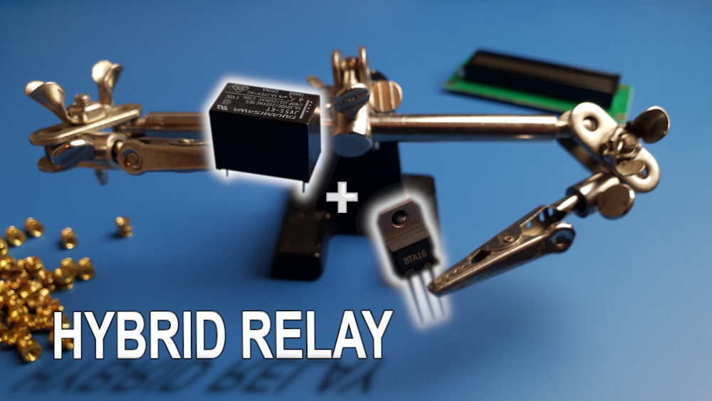
- Hybrid Relay
Introduction
In this article, I will show you several ways how to safely and reliably control Mains voltage with any microcontroller. I compare it with each other and tell you what their strengths and weaknesses are. I will also tell you about real applications in which you can use these methods.
Before we begin, let me briefly introduce you to the “stars” of this article. Due to the fact that this is only a comparison, I didn’t describe all the details. Each of these devices has its separate article, in which I delve into the technicalities.
So if you want to know how it works, what is the internal structure, and if you want to get tested schematics, these detailed articles are for you.
- Electromagnetic Relay (EMR) – is a device that uses a magnetic field to switch the circuit. The most crucial element is the coil. If current flows through it, it turns into an electromagnet, which attracts contacts that close or open the circuit.
- Solid State Relay (SSR) – From the user’s perspective is very similar to Electromagnetic Relay. But unlike EMR, there are no moving parts in SSR.
- Triac – Just like a regular relay, you can think of it as a switch. However, it cannot be connected to the microcontroller directly. You need an intermediate device to be able to control it, and separable from the GPIO.
- Hybrid Relay – is a combination of electro-mechanical and semiconductor technology. It uses the advantages of both. The main benefits are a minimal voltage drop, high durability, and no interference generation.
Which method for controlling AC Mains is the best?
Unfortunately, there is no definitive answer to this question. Each of these methods has its pros and cons. Seemingly, they have the same functionality, but they serve different purposes. To make your choice easier, I divided it into several categories. In each of them, I tried to determine the “winner” and the “loser”. You must choose which of these features is most important to you.
Category 1: maximum current
The maximum current that can flow through the device depends on the maximum power it can emit. In other words, the lower resistance, the lower the amount of heat, and the higher the current is allowed.
Therefore Electromagnetic and Hybrid Relay definitely win in this category. The mechanical contacts have the least resistance. They will withstand 20 A and even more, without any heat sink. To use the Triac for such high current, you would have to install a large heat sink. SSR is usually enclosed in a housing that doesn’t allow the assembly of a heat sink. The maximum current is usually 2 – 5 A.

Category 2: Lifetime
In this case, semiconductor devices perform best. Both Triac and SSR (if you use them correctly) have almost infinite lifetime. They don’t have moving parts, so there is nothing to break.
Electromagnetic Relay looks the worst in this juxtaposition, especially if you want to switch the high load, and you want to do it often. The switching can cause arcing and sparks, which damages the Relay contacts.
The intermediate solution is the Hybrid Relay. It reduces to almost zero the burning of contacts, which is the main reason for the short life. But it still has moving parts, so it isn’t as durable as SSR or Triac.

Category 3: type of voltage
Triac and Hybrid Relay work only with VAC. It results directly from the construction of the Triac, which can be turned off only when the current in load circuit drops to (near) zero. Therefore, with alternating current, it can be turned off every 10 ms (or 8 in the US). I wrote a lot more about this in articles about Triac.
SSR may have various structures. It can, therefore, be adapted to VAC or VDC – never both.
Electromagnetic Relay leads in this category. Both AC and DC work equally well.

Category 4: noise generating
The amount of generated noise depends a lot on the moment at which the load circuit is switched. At AC Mains, the voltage changes periodically. So it is possible that the circuit will close at a peak when the voltage is 325 V (or 180 V in the US). Such a rapid voltage increase (from 0 to 325 V) causes great interference.
That is why the Zero Cross Detecting unit was invented. You can find a nice description on Wikipedia. But in short, it does precisely what its name says 🙂 Thanks to it, the switch-on moment occurs when the voltage is close to zero. This definitely improves the quality of the control.

Because of the delay that Electromagnetic Relays have, it is practically impossible to hit a consistently at “zero” moment. However, you can try to measure the time between powering the coil and closing the contact and try to hit into the right moment. It will not be perfect, but this way, you will reduce the generated interference. And as a bonus, you will extend the relay’s life 🙂
The best in this comparison are semiconductor components. Their delay practically doesn’t exist so that you can choose the closing moment with high precision. That is why SSR, Triac, and Hybrid Relay receive the highest rating from me.

Category 5: control methods
When it comes to alternating current, there are three of the most common methods of control.
ON/OFF Control
It is the easiest method, and often more than sufficient. Both EMR and SSR are basically created for this type of control. If you are going just to switch the light at home, this is exactly the method you need. Here you don’t need Zero Cross Detector because the switching is so rare that you can turn a blind eye to the interference. Of course, you can use the SSR with the ZCD circuit built-in, which will only improve the quality of control.

Phase Control
This method is a little more complicated. But it allows the most precise power regulation. This time ZCD is needed because you need to specify the point in the phase Triac should be turned on. For example, if you want to get 100% power, turn it on as close to zero as possible. If you need only half the power, delay the Triac switching ON by 5 ms (or about 4 ms in the US).

In most tutorials and guides on the Internet, you will learn that you can use this method to dim the light… I think I won’t make a big mistake if I say that for most light bulbs these days, this will not work. Currently, the world is moving towards LED lighting. In that case, by adjusting the phase on the power supply, you can at most get a “disco-light”, not nice dimmed light 🙂
Another (much better) application can be motor speed control. If you need smooth power regulation, this is the best method. However, you must remember about the interference generated during switching at peak voltage. That’s why I just don’t like this method. I think that in most cases, Cycle Control is a much better method.
Cycle Control
It is the cleanest way to control. It generates a minimal amount of noise. In this case, you also need ZCD. Only this time, you will always be turning the Triac ON in “zero”. To reduce the power, you will cut whole sine halves. So if you need only 50%, cut every second half. However, if you want to get 10% power, pass one half of the sine wave and nine cut out. This extends the period to 100ms.

With phase control, regardless of the degree of control, the definition is always 10 ms (8 ms in the US). So if you regulate something that requires a high frequency, e.g. a motor, then, unfortunately, the cycle control isn’t for you. However, if you want to control a heating element, its inertia is so large that this method is perfect for it.
Summarizing AC Mains control methods
This time, semiconductors stand out. Electromagnetic Relays have too much delay, so Phase control isn’t an option.
In Hybrid Relays, it is also possible to use Cycle control if one cycle will be long enough for EMR to switch. Make sure that switching doesn’t occur too often because lifetime will be shortened significantly.
SSR (without ZCD) and Triac allow you to use all methods.

Category 6: ease of use
Here is a little subjective category, but I will try to estimate based on the complexity of the schematic and the method of software control. In my opinion, the simplest is SSR. It has optoisolation, you don’t need to use microcontroller pin protection, and you can control it only with the GPIO state (LOW or HIGH).
Right behind SSR is the Electromagnetic Relay, which is practically identical from the software side. However, due to the inductive nature of the control circuit, you have to provide protection for GPIO. It isn’t difficult – I describe it here.
The Triac requires several components around it to be controlled. In addition, if you want to avoid generating noise, you have to make sure that it is triggered at “zero”. It requires an additional optocoupler and knowledge of microcontroller external interrupts.
The Hybrid Relay is a combination of EMR and Triac, so complexity can be described as the sum of these two. Therefore, it received the lowest rating.

Summary

As you can see in the table above, the best method cannot be clearly determined. When designing your device, pay attention to the features that are most important to you.
For example, if you just want to turn ON and OFF a high-power electric heater, and you don’t plan to switch it very often, then EMR will be ideal.
However, if you have interference-sensitive devices nearby, you can use Hybrid Relay for the same application.
On the other hand, if you only want to control the lighting in your home and you want to do it in the simplest way possible, use SSR.
Triac will be useful when you need more complex wey of control e.g. for an electric motor, or (if you have old type light bulbs) as a dimmer.
Related Articles
How Hybrid Relay works? – The Complete Illustrated Guide
The Hybrid Relay is a combination of electro-mechanical and semiconductor…

How to start a Smart Home – Step-by-Step illustrated guide
This is the first article in the series in which…

How to design an enclosure using photogrammetry? – The Complete Guide
In this article, I’m gonna show you step by step…