
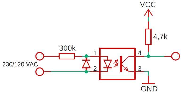
The easiest way to detect mains electricity using a microcontroller is with the optocoupler (optoisolator). It allows you to send information between two galvanically separated circuits. On the primary side, is HIGH voltage: 120/230 AC, and on the secondary LOW voltage, e.g., 3.3 or 5 V. Connect VAC to the input via a resistor/s with a total value of approx. 200 – 300 kΩ and at least 0.5 W. To protect the optocouplers LED, it is good to put a diode (as in the schematic below). The output will usually have a collector and emitter (like in classic bipolar transistor). To the collector, connect VCC via 4.7 – 10 kΩ resistor and emitter directly to the GND. It’s all! You can safely detect high AC voltage with Arduino, ESP8266, ESP32, or any other microcontroller.
The following schematic illustrates what I wrote above. It really is that simple!
For those whose this short answer isn’t enough, let’s dive deeper!
Caution!
Mains electricity is dangerous to health and life! Whenever you do something with it, disconnect the power supply. And before you plug back in, make sure three times that you, your equipment, and everyone around is safe.
Let’s follow the schematic step by step
Input circuit
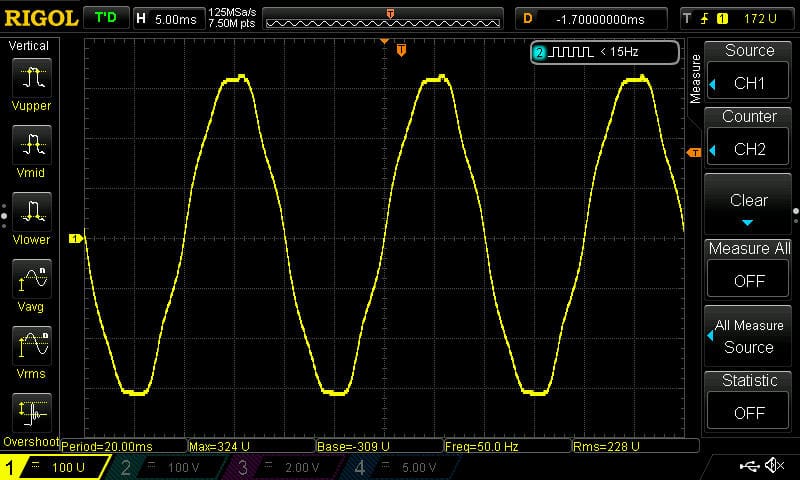
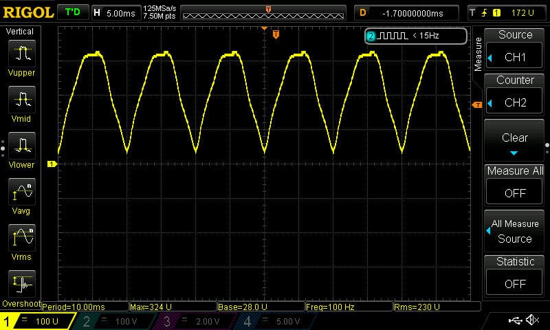
Mains voltage (120 / 230 VAC) on oscilloscope looks like this:
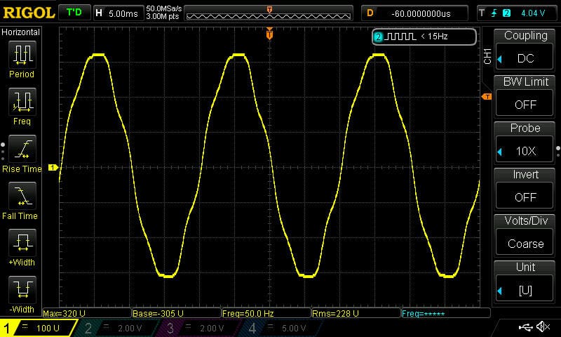
I live in Europe. Here the voltage is 230 AC / 50 Hz. In the US, for example, voltage is 120 AC / 60 Hz. But other than that the graph would be the same.
To safely connect such high voltage to the optocoupler, it is necessary to limit the current. That’s why there is a 300 kΩ resistor in the schematic. If you live in the USA, you can use a lower resistance e.g., 200 kΩ.
Important!
Because the voltage is high, you must consider the max power emitted by the resistor. You can calculate this using the following equation:
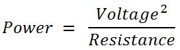
In my case, it’s 0.35 W. It’s good to have some safety buffer. That’s why in the first paragraph, I wrote 0.5 W. But still be aware that this resistor will be warm. Don’t close it in a small, sealed housing, ensure some airflow.
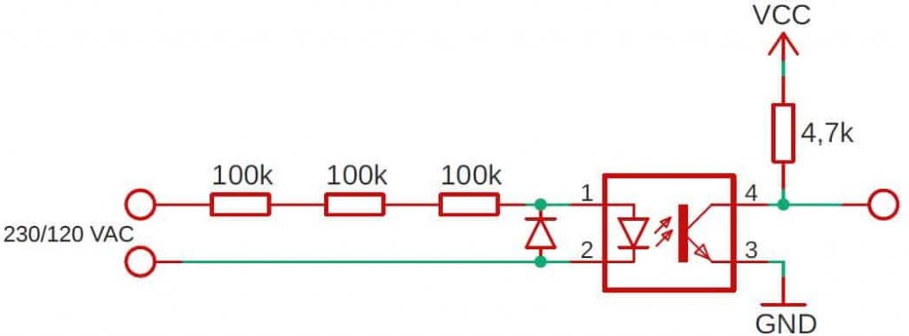
A good idea, which I highly recommend to you, is to use two or even three resistors in series. In this way, the power is distributed over several components instead of one. Secondly, and even more important is the maximum voltage that the resistor can take. For small cases will be easily exceeded.
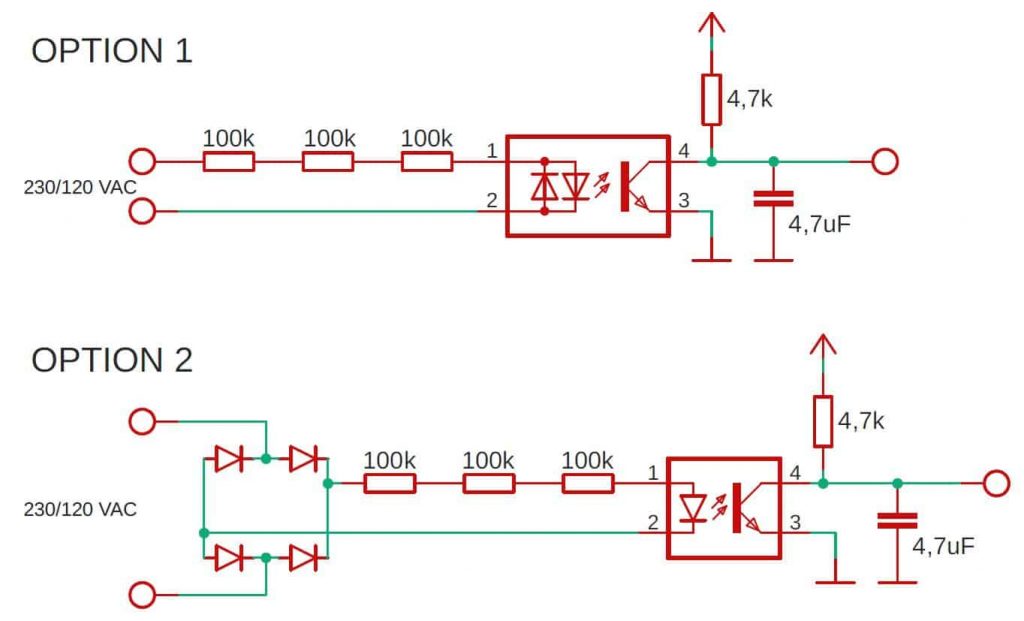
The upgraded schematic looks like this:
Output circuit
The secondary side of the optocoupler is galvanically separated from mains electricity. There you can safely connect the GPIO of the microcontroller.
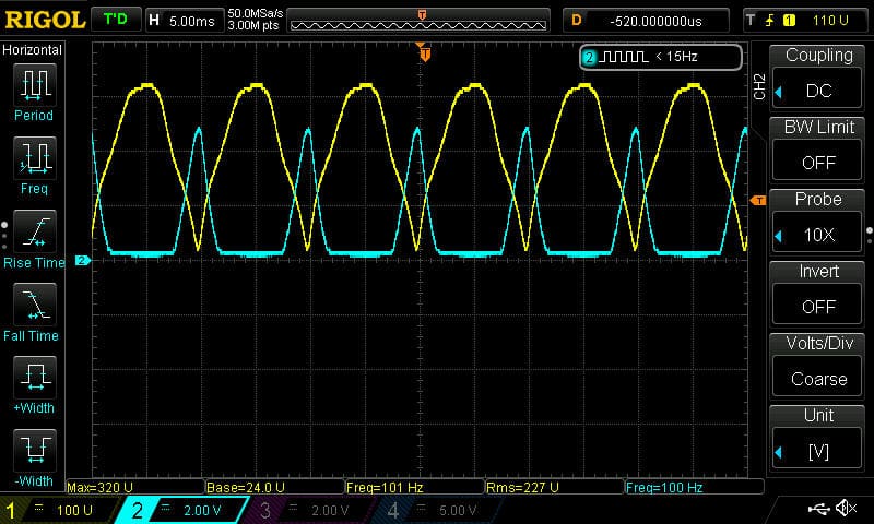
You must be aware that there is no “nice” DC voltage on the output. Instead, there is a square wave.
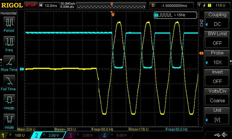
In the graph above, I showed the moment of turning on the power. Yellow chart is the input to the optocoupler, and blue is its output. As you can see, when the input voltage is zero, the output is high. In this case, 5V.
When the alternating current begins to flow, the voltage changes from +325 to -325 V (in my case). If the voltage exceeds about +1.3 V (forward voltage of LED in optocoupler), it lights up. You can treat it as if you were starting to apply voltage to the base of a transistor NPN. When a sufficient voltage is used, it acts as a short circuit. The output drops to the GND level. Similarly, when no voltage is applied at the base, the transistor operates in the cutoff region and acts as an open circuit. The output is pulled up to VCC.
What are the pros and cons of such output?
It depends on how you look at it and how you want to use it. If you plan just to check if the current is flowing, you cannot just check the pin status from time to time. There is a high probability that you will hit “in-between” as if there was no mains electricity. Of course, there are plenty of ways to solve it in the software. I will present one solution below. I used it in one of my previous projects, and it works very well.
On the other hand, this kind of output has a significant advantage if you care about “Zero Cross Detection”. I will explain this in more detail in another post. Here, I’ll make just a little introduction.
Zero Cross Detection
Zero Cross Detection (ZCD) is a prevalent method of measuring frequency. For example, you can use this instead of a crystal oscillator to measure time. In the long run, the frequency is very stable. As you can see above, the frequency is exactly 50 Hz.
Another important reason to use this is EMC (electromagnetic compatibility). This is crucial when you want to fairly often switching on/off a high load e.g., an electric heater. You can find more about EMC on Wikipedia.
I want a steady and smooth DC output!
If you don’t care about Zero Cross Detection and you want to check the GPIO status at any time and be sure that mains electricity is present or not – the following schematics upgrade is for you.
As always, in the engineering world, there is more than one solution for every problem. I will introduce you to one of the simplest. I divided this thread into two stages: first, we will cut off the negative part of the input voltage, and then we will smooth it out.
Step one: cutting off the negative part of the sine wave
Being more precise, we will not cut the negative part completely. We will transform it into a positive one. The main disadvantage of the first circuit is that we use only half of the sinusoidal waveform – only the positive half. When the voltage is below zero, the optocouplers LED doesn’t light up. Fortunately, there are simple methods to fix this.
Let’s add four diodes (so-called Graetz bridge) to the scheme. This is a two half-period rectifier.
In this case, we no longer have a negative voltage, i.e., the protection diode (as in the first example) is no longer needed.
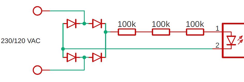
With this little upgrade we changed this:
into this:
An alternative solution is to use a bidirectional optocoupler. It has two LEDs conducting in opposite directions. Thanks to this, the effect on the secondary side will be very similar to the use of a rectifier.

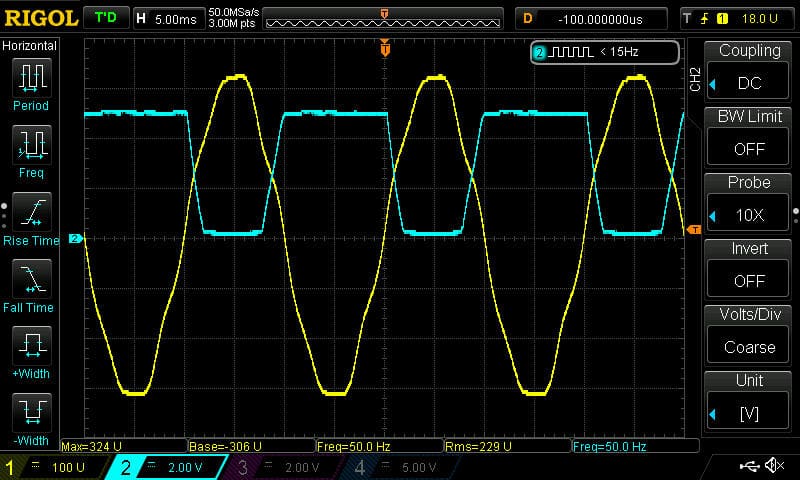
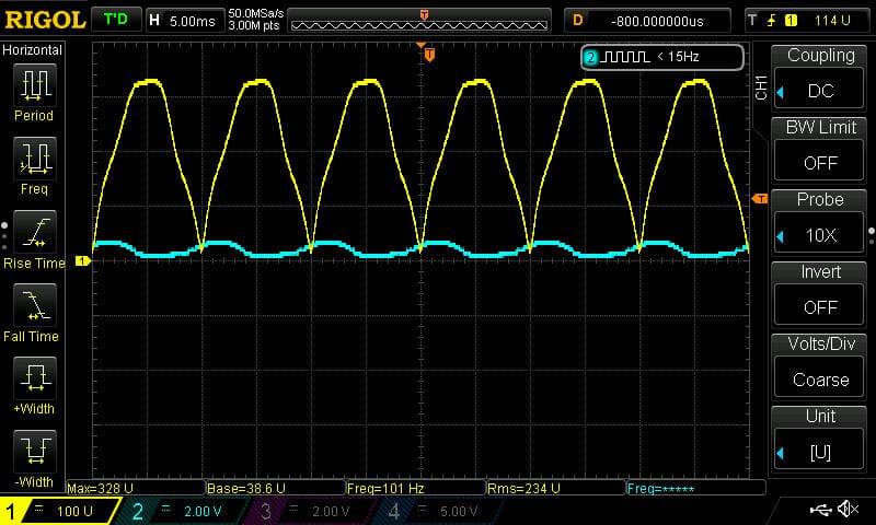
This time the output signal looks like this:
Step two: smoothing the output
Let’s make the graph smoother. To do this, we will add a capacitor between the Emitter and GND. Its capacity isn’t critical. Values between 2 and 10 uF will be right in most cases.
Below are the final versions of the schematics. Both will give you practically the same result, so choose which one you prefer more.
On the oscilloscope, output doesn’t look perfectly flat, but the fluctuations are less than 0.5 V. For every microcontroller, voltage will be smoothed enough.
Software
In the simplest version of the circuit (the one that I showed at the very beginning), checking GPIO status from time to time is a bad idea. There is a big chance that you will check it when the status indicates: “no voltage”. Therefore, a better solution is to use external interrupts. Nowadays, all microcontrollers are able to do this. I wouldn’t like to go into the implementation details, because it depends on the uC you are using. You have to look into the datasheet there for sure everything will be explained.
In the version in which we used the rectifier, the matter is much simpler. You can check the pin status at any time and know if VAC is present or not.
Summary
In this article, you learned how to detect mains electricity safely using a straightforward circuit. As you can see, you don’t need any complicated and expensive chip or integrated circuits to understand which you need a Ph.D. in electronics 🙂 The most ordinary optocoupler, several resistors, a diode, and a capacitor do the trick.
I have presented you with only one possible way. As always, there are many other solutions to this problem. They are better, worse, simpler, and more difficult, but I focused on the one I use and with, and I can recommend it to you, with a clear conscience. I hope it will be useful for you.
Greets!
Related Articles

How to start a Smart Home – Step-by-Step illustrated guide
This is the first article in the series in which…

How to program STM32 – The Complete Guide
In this article, I’m gonna show you how to program…
How to control AC voltage with a microcontroller?
To control AC Voltage (usually AC Mains) with a microcontroller,…