
Do you know this feeling when you go to bed and wonder if you closed the garage door? I had that countless times. So I went down every time in my pajamas and checked, otherwise I wouldn’t fall asleep.
Once I decided that I had enough! We have 21st century! I have a lot of smart devices at home, why not have a smart garage door opener? There are many solutions on the market. But they are way too expensive. And being entirely honest, they are hardly functional in most cases. There are also DIY projects. Unfortunately, they usually look like very early prototypes. I don’t like tangled cables. I design electronics daily, so why not create something yourself in this case? Long story short, I present you SS4H-GO, my smart garage door opener.
If you also want to have a “smart” door in your garage, this article is for you. I’ll give you my source files and tell you precisely what you need to do to make it happen.
Introduction of SS4H-GO Smart Garage Door Opener
Before we get started, let me give you a small introduction. I promise I’ll be as brief as possible. But if you can’t wait to start creating just skip it.
The main inspiration for my project was a DrZzs’s movie about controlling the garage door using wifi and Home Assistant. Btw. if you don’t know this guy, you absolutely must visit his channel! He does a really good job with his videos of “Smart DIY stuff”.
His garage door opener is great – however, I wanted to add some features to it. If you are designing your PCB, you have much fewer restrictions than using something off the shelf. So I decided to add as many functions as I could. I also wanted my version to be small and easy to assembly on most garage doors.
In that way, after a few weeks of prototyping and a few failures, SS4H-GO was created. And I have to admit I’m proud of it 🙂
Video version
I have also made a video showing how my device works. If you aren’t sure if this project is for you, watch the video first, then read the article.

Main features
- The most obvious function is to open and close the garage door.
- Making sure your precious car is in the garage.
- Checking if the door is actually closed or if someone has opened it by force, e.g., with a crowbar.
- Making temperature and humidity measurements. Maybe you have pantries there? Or you brew beer, and the temperament must be appropriate?
- Checking if the light is on. You can find out if someone is wandering at night with a flashlight near your pantry (or worse, beer!) 🙂
- You can also connect any binary sensor you want, e.g., smoke detector, additional motion PIR sensor, traditional manual switch, or anything else.
How do I get this garage door opener and how much does it cost?
I will answer these two questions in engineering style… It depends. You can do it yourself: “DIY way“, or you can buy it assembled and tested: “FAST way“.
On the other hand, if you prefer to hold a soldering iron instead of a pen (like me), print more in 3D than 2D, have some perseverance and manual skills, or you simply want to learn all of this, “DIY way” is your way. Don’t skip the Hardware paragraph in that case.
The price depends on you. I will give you all the materials to create SS4H-GO for free. You need to buy components, make a PCB, and print the case
Necessary additions
- In addition to the device itself, you will need a USB-UART adapter. If you flash any ESP8266 modules before, you probably already have it. If not, unfortunately, you have to get it somehow.
- Some kind of switch allows us to detect if the door is closed, e.g., magnetic one.
- You also need a 5/12V power supply.
Hardware
Finally! I know you couldn’t wait anymore to start 🙂 I have divided this chapter into several parts. In the first three stages, chronology isn’t crucial. However, I recommend you start with the ones that take the most time. For example, if you want to order PCB, do it at the beginning of the project. You will be able to do something else while you wait.
You will need a few files to make this project happen: schematic, PCB layout, 3D model of case, and configuration file. If you want to receive all of this, just enter the e-mail below – I will send a link to you straight away.
PCB
I assume that you already have all the files locally on disk. Let’s start with PCB.
These are GERBER files – the most popular format in the PCB’s world. Any company that makes printed circuit boards knows it for sure. If you are going to make a board by yourself, I recommend a great article: “How to Make a Printed Circuit Board“.
The sponsor of this project is JLCPCB. They made the board for this project. For a few bucks, and in a matter of days, you can have a professional-looking PCB in your home. And if you don’t feel up to it, they can solder all SMD components for you.

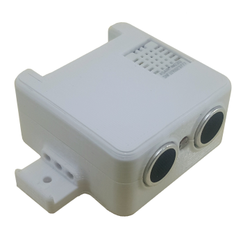
3D printed case
The procedure is similar to making a PCB. You can print it yourself or order it somewhere. In both cases, you will need an STL file. Unfortunately, I don’t have a helpful article to recommend. There is simply too much of it. If you own your 3D printer, I’m sure I don’t have to explain anything, if you don’t have one you need to order it anyway.

Shopping
The cost of your Smart Garage Door Opener depends most on this stage. You can buy most on Aliexpress, then it will undoubtedly be the cheapest, but you will have to wait a bit for delivery. You can also buy it all at your local electronics store. It will be more expensive, but you won’t have to wait. The choice (as usual) is yours.
Assembly PCB of the Smart Garage Door Opener
It is my favorite part of every project. I have a fresh PCB in my hands, all the components are waiting in the box, the printed schematic is on the desk, and the soldering iron is hot 😉
If you are just starting your adventure with soldering, I highly recommend you: How To Do SMD Soldering Using a Soldering Iron
Details
- I don’t think I need to introduce the ESP8266 module. You can buy it here: Aliexpress.
- Start assembly from the smallest components: resistors, capacitors, LED, and so on. If you start with the big ones (HC-SR04 or relay), then you will have difficulty manipulating the soldering iron later. You can buy the HC-SR04 sensor on Aliexpress.
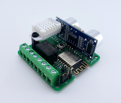
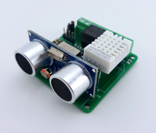
- The DHT22 (Aliexpress) sensor should be far away from the heat-generating components to make temperature and humidity measurements as correct as possible. Unfortunately, this component has short “legs”. Therefore you have to solder the wires to extend it. Then screw on the spacer and bend the legs. Now you can mount the sensor on the PCB.


- The photoresistor must also have bent legs and be mounted at the correct height. Guided by the saying: “a picture is worth more than a thousand words,” just do it as in the pictures below.
The rest of the components are standard, and their assembly is straightforward, so I think that now you can handle it yourself.
The finished SS4H-GO Smart Garage Door Opener should look like this:
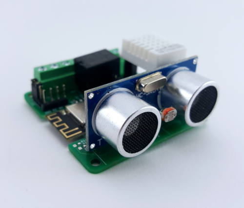

Congratulations!! You’ve done the most difficult and time-consuming part of the project. You can be proud of yourself!
Software
In this chapter, I will show you how to integrate SS4H-GO with (in my humble opinion) the best open source HUB for smart homes – Home Assistant. Of course, if you are using openHAB or Domoticz, you can use this garage opener too. The ESP8266 module is very popular and is fully compatible with probably all open systems. However, in this article, I will focus on Home Assistant.
This paragraph is for people who have never flashed ESP8266 chips (e.g., Sonoff module) or who don’t know the ESPHome plugin. If you have done it before, you can easily skip this paragraph, I don’t want to make you fall asleep 🙂
ESPHome installation
A full description of how to install ESPHome step by step, you can find on the official website. There is a lot of information and even more examples. If you ever have a problem with some ESP module solutions start looking right over there.
Adding Smart Garage Door Opener to ESPHome
- Click the large green circle to enable the wizard that will guide you through the entire process.
- Enter the name of your device. This name must be unique for each device in Home Assistant. For me it will be “ss4h_garage_opener” – no funky characters! 🙂 Only “a-z”, ‘0-9 “and” _ “allowed.

- Select devices from the list – “ESPRESSIF ESP-12E module”. In fact, this choice doesn’t really matter. ESPHome uses this only for mapping pin names. But, let’s choose the correct one for the sake of principle.

- Enter the SSID and PASSWORD of your WiFi network. You can leave “Access Password” blank.

- Just click SUBMIT button on this page.
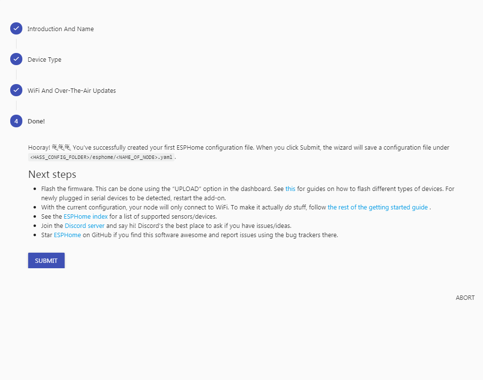
As you can see, a new item with the name you gave before has appeared. It is offline now, but we will change it soon.

It is necessary to reset the plugin. ESPHome at startup will generate a configuration template for your newly added device. To do this, click: Supervisor -> ESPHome -> Restart. As soon as it turns on, reopen the web interface (the easiest way is just to click: OPEN WEB UI).
Configuration ESP8266 module
Now you can edit the configuration file. You should see something like this:
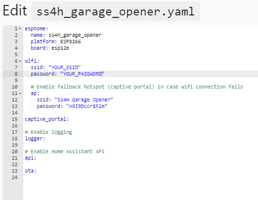
It is the automatically generated template. Let’s add all your sensors from the door opener.
The configuration file is super important, and there can be no errors in it at all. Therefore, let’s follow this config carefully sensor after sensor. But don’t worry, I won’t force you to write the code manually, I’m not a monster 🙂 You’ve probably found the configuration file on the download page you received in the email so you can use “ctrl + c”, “ctrl + v”.
Momentary switch
Most garage door motors can be controlled with a wall-mounted momentary switch. You can simulate it with a relay. This solution has a big advantage. It can be used independently of an actual existing momentary switch.
That is why first I assigned pin GPIO5 as a binary output connected to the relay, and then I create TEMPLATE, that every time when RELAY is activated ESP waits 200 milliseconds and disables it.
switch:
   -  platform: gpio
       pin: GPIO5
       name: "Door relay"
       id: relay
     - platform: template
       name: "Momentary switch"
       id: "trigger"
       turn_on_action:
       -  switch.turn_on: relay
       -  delay: 200ms
       -  switch.turn_off: relay
Magnetic door sensor
It doesn’t have to be a magnetic door sensor. You can connect any two binary sensors. In my case I used two magnetic sensors. One when the door is completely closed and the other when it is completely open. You absolutely don’t have to do that. One sensor (when the gate is closed) is enough. You can connect something else instead, something more useful, e.g. smoke detector or CO² detector. I did that because I have already connected the smoke detector in a different way.
Configuration of this element comes down only to assign the appropriate pins (GPIO13 and GPIO14) as an input to the ESP8266 chip. I think I don’t have to explain the “inverted” filter. On the other hand, the “delayed_on” filter may not be so obvious. I used to eliminate switch debouncing.
binary_sensor:
   -  platform: gpio
       pin: GPIO14
       name: "Gate is open"
       id: up_endstop
       filters:
         -  invert:
         -  delayed_on: 20ms
    -  platform: gpio
        pin: GPIO13
        name: "Gate is closed"
        id: down_endstop
        filters:
          -  invert:
          -  delayed_on: 20ms
Text sensor
The configuration of this “text sensor” results directly from the fact that I have two “door sensor”. That is why I can detect if the garage door is closed, open or somewhere in between. So I have a “sensor” with three possible states. The “text sensor” is ideal in this case.
Configuration, unfortunately, isn’t so simple and obvious. ESPHome allows you to write C ++ code in a configuration file. That’s what “lambda” is for. If you want to know more, I recommend you LINK.
text_sensor:
    -  platform: template
        name: "Gate status"
        lambda: |-
            if((id(up_endstop).state)==(id(down_endstop).state)){
                return {"between"};
             }else if((!id(up_endstop).state)&&(id(down_endstop).state)){
                return {"closed"};
             } else {
                return {"open"};
             }
         update_interval: 5s
Ultrasonic sensor
I used the popular HC-SR04 in the garage opener. It is cheap and reasonably reliable. It measures (as you certainly know) distance. Knowing that we can determine whether the car is in its place or not.
Two pins are used by this sensor. “Trigger” to initialize the measurement and “Echo” from which the result is read.
sensor:
    -  platform: ultrasonic
        trigger_pin: GPIO2
        echo_pin: GPIO12
        name: "Ultrasonic Sensor"
        id: car_presence
        update_interval: 1min
Car presence
The “HC-SR04″ ultrasonic sensor gives a precise distance. However, we are only interested in whether the car is in place or we should call the police because someone stole it.
Therefore we have to set a threshold. In my case, if the car is in place, the measured distance is about 0.5 m. That’s why I set the 1 m threshold. If it is less than 1 m it means that the car is where it should be.
binary_sensor:
 ……
    -  platform: template
       name: "Car presence"
       device_class: presence
       lambda: |-
           if (id(car_presence).state < 1) {
              return true;
           } else {
              return false;
           }
Light sensor
This is a simple photoresistor and it is connected through a voltage divider to the ADC converter.
I used the C++ code to scale the result to something more reasonable. I wrote “lux” as a unit – because I measure the intensity of light, but be aware that the result doesn’t have much in common with real “lux”. Of course, nothing prevents the sensor from displaying precise values. It would be best to compare it with some professional meter to achieve it.
sensor:
 ……
    -  platform: adc
        pin: A0
        name: "Garage Light"
        unit_of_measurement: "lux"
        filters: lambda:
        -  return x * 1000.0;
        update_interval: 1min
Temperature and humidity senor
Last but not least is the DHT22 temperature and humidity sensor. You are probably wondering: “why does he need so many filters?”. They simply smooth the sensor readings. Thanks to this, I have a nice, not jagged chart. Of course, if you want more frequent measurements, you can modify the parameters. All filters are explained on the ESPHome page.
You need to pay attention to one more thing with DHT22. Each sensor is different and shows different values. It’s annoying but unfortunately, it is so and you can’t do anything about it. Therefore, it would be ideal if you could compare the indications with another thermometer and hygrometer. And if there are any differences use at least the “offset” function.
sensor:
 ……
    -  platform: dht
        pin: GPIO4
        model: DHT22
        update_interval: 1min
        temperature:
            unit_of_measurement: "°C"
            name: "Garage Temp"
            filters:
                - offset: -1.0
                - sliding_window_moving_average:
                    window_size: 15
                    send_every: 15
                    send_first_at: 15
         humidity:
             name: "Garage Hum"
             filters:
                 - sliding_window_moving_average:
                     window_size: 15
                     send_every: 15
                     send_first_at: 15
General remarks for configuration file
- Some sensors have a verse “update_interval: ..” and others don’t. Without going into details, to not complicate it unnecessarily: the change in the state of the binary sensor is known immediately, other sensors are read from time to time. You can change this time, but don’t reduce it too much. With each update, a message (MQTT) is sent via your WiFi network to the router. If you have a lot of different devices and all are trying to send or receive something, you can fill most of the bandwidth. Therefore, change the intervals with common sense.
- When you will be modifying this config, focus on indentation in the code. In “YAML” files, they are very crucial.
- This is my configuration to suit my specific case. If you go a little deeper into the subject, you may want to write the configuration in your way, and that’s good, I encourage you to do it. Treat the above instead as an example from which you start and which you can “almost” freely modify. Do not change the numbers and pin names. It results directly from the schematic itself. Besides that, do what you want. You can always come back to this example if something goes wrong.
Generating configuration from ESPHome
It is good practice to make sure that there are no errors in the code every time you make any changes. Locate the validate button and use it. Be aware that this tool doesn’t check all errors. I mention that you can write code in C ++, isn’t it? These configuration parts are unfortunately, beyond the reach of tools for error checking. Nevertheless, I recommend that you use a validation function every time. If everything goes well, you can click close.
Let’s generate a binary file now. To do so, expand the menu (three dots icon) and click compile. It may take up to 2 minutes. The file download will start automatically after this.
Flashing ESP8266
In this paragraph, I will tell you how to breathe life into your Smart Garage Door Opener. The device’s brain is the ESP8266 chip. And although it is quite powerful, you have to “tell” it what to do. He will not guess himself 🙂
You need the configuration file you just created, the USB-UART adapter, and a small piece of software. I recommend ESPEasy. I use it for a long time, and it hasn’t disappointed me yet. You can download it here. Nevertheless, you can use any program that allows you to upload binary files via UART.
Connecting USB-UART adapter with Smart Garage Door Opener
- There are programming pins on the PCB: VCC, TX, RX, and GND. The USB-UART adapter has the same pins. Connect it as follows:
GND -> GND, VCC -> VCC (or 3,3V), RX -> TX and TX -> RX.
Be careful, don’t connect VCC to 5V – you will most likely kill the ESP chip!

- You can now connect everything to your computer, but before you do this, press and hold the flash button. This way, you tell ESP that it will be programmed. If you don’t do this, the programming will fail. Of course, you don’t have to hold it all the time. Do this only when you connecting the power supply (USB plug in this case).
- If you are using ESPEasy, go to the directory where it is located and copy your configuration file generated by ESPHome there.
- Now you need to figure out what number your computer gave the adapter. In Windows, turn on the “Device manager,“ and in the “Ports (COM and LPT)“ tab, you should find your device. On iOS… I don’t know 🙁 If you’re using Apple, you will find information for sure on how to do it.
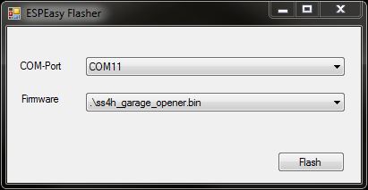
- Once you know this number, turn on ESPEasy Flasher. From the “COM-Port” select the correct port, select your file from the “Firmware” drop-down list and then click the “Flash” button.
- Now you have a small break. You can comfortably sit back and watch your smart garage door opener is programmed. If everything went as it should, after a while, you will see the message: “Flash Complete“.
Integration with Home Assistant
It’s time to integrate Smart Garage Door Opener with Home Assistant. I will show you how to make a simple interface to operate the relay and read all sensors. It will not be something fancy. I will focus on functionality. I am sure that you will later make something beautiful out of it.
Restart your device first (just turn the power off and on). In the ESPHome user interface, you should see that the device has changed its status to online. If not, give it a moment.

Home Assistant should automatically detect a new device. If so, enter the Integrations menu. You will see something like this:

If you don’t see anything like it there, don’t worry. It’s a straightforward way to add a new interaction manually. To be honest, I don’t know what it depends on. Home Assistant once detects new devices by itself, and other times you need to add them manually. Nevertheless…
Click the “plus” icon in the bottom right corner. Select ESPHome from the list of interactions. The hostname is the name you provided when generating the configuration file + “local”. In my case, it is “ss4h_garage_opener.local“. Leave the Port default. After clicking Submit you will see a message confirming that everything went fine. Then you can choose which area you want to add it to (kitchen, living room, bedroom, etc.), if you don’t know, just leave it by default.
Setting up Entity
Let’s create a dashboard, your garage control center. You’ve probably done it many times, and you already know it, but I’ll write it anyway 🙂 Click Overview -> Configure UI -> plus icon -> ENTITIES. You will see a graphic entity editor called: “Entities Card Configuration“. Start by giving the title, then add all sensors and switches from Smart Garage Door Opener. The drop-down list includes all devices (entities) that are integrated with your Home Assistant. Locate all that interest you.
In my case it looks like this:
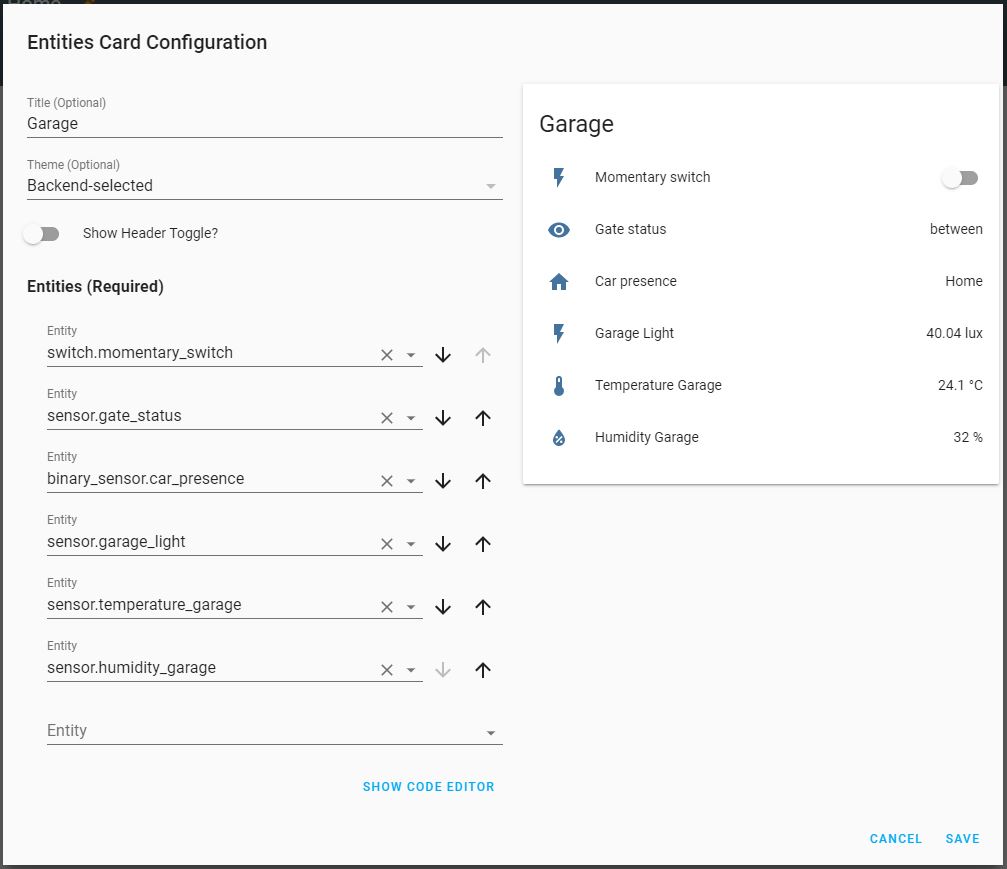
Congratulations, you have a fully functional control panel for your SS4H-GO!
I told you before that I leave it to you to make a beautiful, but let’s improve it gently. Only names and icons. Click SHOW CODE EDITOR. Here you can also add, delete, and modify entities. You can change it much more here than in the visual editor. Let’s use it now, but instead of writing how to do it, it will be easier to show it by example.
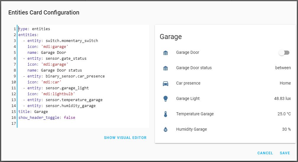
I added the “name” and “icon” commands to the entity that I wanted to change. As you can see in the preview icons and names, I have adjusted accordingly. You can find a list of all available icons on the Material Design Icons page.
Final testing
Now is the perfect time to test the device. You have it close to you, and the case is open, you don’t have to go to the garage and climb the ladder to remove it.
You can check if the temperature and humidity shows the correct values if the light changes depending on whether you turn off or turn on the light and so on. Unfortunately, you won’t be able to quickly check if the relay is working. You must connect a 5V or 12V power supply. If you are now powering everything from a USB-UART adapter, the relay will not work. The voltage is too low. If the adapter you are using has 5V, you can use it for power supply, but remember to set the jumper on the PCB to “5V”.
If you are satisfied with the test results, you can move on. You’re almost done!
Case assembly
There will be the shortest chapter. I assume that everything is working correctly. Now you can close the case. Just screw in 4 screws, and that’s it. You are ready for the final assembly.
Installing the smart door opener in the garage
This is the final step! 🙂
This chapter is about the integration of my SS4H-GO with my door. It will certainly look a bit different in your garage. You must be flexible and inventive. But since you have reached this stage, I am sure you will manage. This time I won’t tell you what to do, I will say to you and show what I did in my garage. It can be an inspiration for you.
Power supply
I started by preparing the power supply. In my case, when the house was being built, I made sure that there will be a 12 VDC power supply near the gate drive. So the connection was super easy.
In your case, it probably won’t be that easy. However, at 100%, you will have near 110/230 VAC. You can use an ordinary 5 V or 12 V power supply.
Caution!
- Do not swap VCC with GND!
- Set the jumper on the PCB accordingly to the power supply (5V or 12V)
- When you do anything with any electric device, remember – disconnect the power supply first! It is a risk of electric shock!
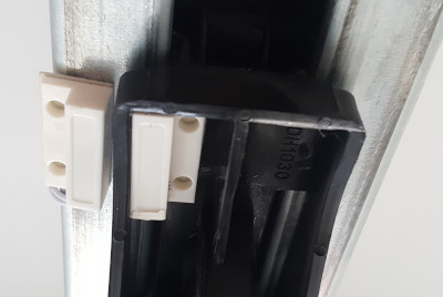
Installation of the Smart Garage Door Opener at the actual gate
In my case, it was easy to attach everything to the main rail. I used cable ties for this.


Magnetic door sensors that I bought have double-sided tape in the package, so I used it and it stays for almost 2 months now. So I think it won’t fall off 🙂

Wiring
I just connected everything according to the diagram below.

And that’s all 🙂

Summary
Congratulations! You probably already have a fully functioning Smart Garage Door Opener in your home. You can now create any automation that will make life easier for you and your family.
I wanted to thank you very much for persevering to the end of my guide. It doesn’t matter if you chose “DIY way” or “FAST way“, please don’t be shy and let me know how it turned out. I’m inquisitive.
If you have any questions or comments, you can just send me an email to: contact@smartsolutions4home.com.
Related Articles

SS4H-ZRG Zigbee Rain Gauge – DIY project based Zigbee Door Sensor
In this article, I’m going to show you how to…

SS4H-SSR Smart Extension Board – DIY project based on ESP8266
With these kinds of projects, they are often created when…

SS4H-SHH Smart Home Hub based on ESP32 POE
Personally, I’m a fan of centralized “smart” systems. Thanks to…