

A Stepper Motor is a brushless DC motor that converts electrical impulses into mechanical motion. Each impulse is a rotation of the ROTOR (a moving part of the motor) through a small angle (step). For example, if the stepper has 200 steps per revolution, then after giving 50 impulses, it will make a quarter turn. The frequency and sequence affect the direction of rotation and its speed.
Introduction
Stepper Motors are often used in devices that require high precision. You can find them in CNC milling machines, 3D printers, robots in factories, scanners, or CD/DVD drives (if you’re old enough to remember it 🙂 ). Steppers are really grateful and pleasant devices that will surely find a place in many of your projects. They are also very easy to control, as I’ll try to show you in this article.
What is a stepper motor?
A Stepper Motor is a brushless DC motor. As I mentioned earlier, it’s powered by electric impulses, which are converted into rotary movement. The rotation isn’t smooth as with classic DC motors. A full 360-degree rotation consists of a certain (depending on the construction) number of steps. This allows the shaft to be rotated precisely without any feedback. So no encoder is needed.
In the hobby world, Stepper Motors with 200 steps per 360° are the most popular. This means that the shaft (the rotor) will turn 1.8° each time we give an impulse (360° / 200 = 1,8°).
The direction of rotation and its speed depending on the sequence and frequency of the impulses.
How is a stepper motor built?
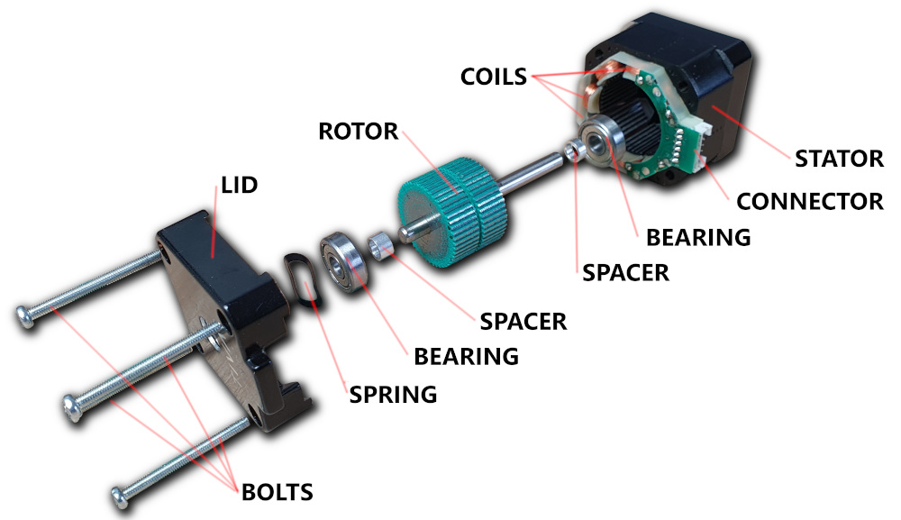
A Stepper Motor, like a classic DC motor, consists of a ROTOR and a STATOR. The stator is a stationary part, while the rotor mounted on two bearings rotates with a magnetic field. Stator – made of steel or other metal, it’s the frame for a set of electromagnets which are coils mounted in specific places around the rotor. When current flows through the coils, a magnetic field is created around them. The individual magnetic fields have the direction and intensity depending on the intensity and direction of the current flowing through a given coil.
Types of stepper motors
Stepper motors can be divided due to the construction of the stator and rotor, which affects how pulses are converted into motion. And because of the way the coils are connected.
I’m gonna describe these two factors separately as they are completely independent of each other. Any type of connection can be used with any type of motor.
Due to the construction, we can distinguish:
- Variable reluctance stepper
- Permanent magnet stepper
- Hybrid stepper
Due to the method of winding, we can distinguish:
- Unipolar stepper
- Bipolar stepper
How does a Stepper Motor work?
Each type works a bit differently, so I’ll describe them separately. Starting with a variable reluctance motor.
Variable reluctance Stepper Motor
Motors of this type don’t have good parameters and have been pushed out of the industry by other types of steppers. I’m gonna tell about them for learning purposes. And to help you understand the general principle of operation.
FULL STEP
Reluctance is also known as magnetic resistance. If we place a conductor in the magnetic field of an electromagnet, it will be attracted. The closer it gets, the less resistance will be.
The animation shows an example of a stepper motor with variable reluctance with four coils. They are wound in pairs and on opposite sides of the stator. This gives us eight poles. The rotor is made of some conductor, and the number of arms is different from the number of coils. Since the direction of the pole doesn’t matter in this case, I decided not to mark it.
As you can see, when the appropriate pair of coils are powered, the closest arms of the rotor are attracted the most. This way, one step will be taken. In the case of this stepper, it will be:
6 arms * 4 coils = 24 steps
360° / 24 steps = 15°
15° is FULL STEP for that particular stepper motor. It doesn’t sound very impressive, I know.
HALF STEP
Fortunately, it is possible to increase the resolution very easily. To double the number of steps, we gonna use a HALF STEP instead of a FULL STEP. Sounds intuitive, right? 🙂
To achieve this, we’ve to change the powering sequence of the coils. In the previous case, we only used one pair at a time. This time we’re gonna use two adjacent pairs to make an intermediate step. Now we have 8 combinations (not 4) of powered coils. This means we’ve doubled the resolution to 48 steps and 7.5° for a single step.
Supposedly a picture says more than a million words, so I think that simple animation will explain it even better.
MICRO STEP
But it isn’t over yet! We can increase the resolution even more. For this, we need to be able to regulate the current flowing through the coils. So that it can be powered, for example, with twice less current. Thanks to this, we double the number of possible states compared to the HALF STEP method. Again – animation 🙂
Now, we have 96 steps, and 3.25° per a single step.

In this way, we can increase the resolution more and more. Unfortunately, apart from the obvious advantages, it also has big disadvantages. The greater the number of micro-steps, the more frequently the switching of the coils, thus less torque.
I described the above control methods (FULL, HALF, and MICRO STEPPS) based on a stepper motor with variable reluctance because it is the simplest one. However, it’ll work in the same way for any subsequent type. Therefore, for permanent magnet and hybrid steppers, I’m gonna describe only the FULL STEP method.
Permanent magnet stepper motor
A permanent magnet Stepper Motor works through the interaction of the poles of the magnets. Not as in the previous case – the pole and the conductor. Each of the magnets has two poles:
N – North
S – South
Unlike poles (S – N) attract each other, while the like ones (S – S, and N – N) repel each other. As a result, steppers of this type have a much greater torque.
Unlike the variable reluctance stepper motor, the permanent magnet one has no teeth on the rotor. It is built as if of several magnets alternately and radially magnetized. The resolution of the motor depends on their number. However, the more of these magnets, the smaller they are, so they interact less with electromagnets in the stator. As a result, the motor has less torque.
The following simple example has a rotor with six magnetic poles. With two poles of the electromagnets, this gives 12 FULL STEPS per revolution. In the real world, motors of this type have 24 or even 48 steps.
Hybrid stepper motor
Hybrid stepper motors are currently the most popular type, especially in the industry. They combine the advantages of permanent magnet and variable reluctance motors. Thanks to that, they’ve better parameters like torque and resolution. The resolution of a typical hybrid stepper is between 0.9° and 3.6°, which gives 100 – 400 FULL STEPS per revolution (and let’s not forget that we can also apply MICRO STEPS too).

The rotor is made of permanent magnets, however, unlike the motor described above, the magnets are placed axially and not radially. Additionally, as you can see in the picture, the rotor is divided into two (sometimes four) rings. Each of them has small teeth. The more of them, the greater the resolution.
The teeth on both ends (rings) of the rotor are shifted by half a tooth. The stator also has teeth, but they are in line all the way. Thanks to this, when the teeth of one ring have unlike poles and attract each other, then the teeth from the second ring (having the same pole as the coil) will be exactly in between. This improves the characteristics of the motor and increases its torque.

The stator of such a motor usually has two coils and eight poles. After powering one coil, two opposite poles will be NORTH, and two will be SOUTH. Then, the rotor will rotate to align its magnetized teeth with the, unlike (S and N) poles of the stator.
Because the rotor has two rings with different poles, at each step, it is “held” by four coils, which increases its torque.
On this particular stepper, the rotor has 50 teeth, and exactly 4 steps are required to turn it one notch. Thus, it is easy to calculate that the rotor needs 200 steps to complete a revolution. Which is 1.8 ° per step (FULL STEP).
Unipolar and Bipolar stepper motors
The term unipolar or bipolar stepper motor isn’t entirely precise. It doesn’t apply to the entire motor, but only to the winding of its coils. Although in practice it’s very often possible to clearly determine whether a given stepper is unipolar or bipolar. But you can also come across a stepper motor which can be both: “bi” or “uni”. It’s up to you how you want to treat him.
Therefore, for further considerations, let us assume that it concerns the stepper control method and not its type.
Bipolar stepper motor
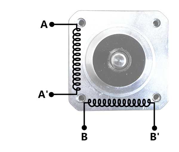
The Bipolar Stepper Motors have four wires. They operate with two windings completely separated from each other.
These steppers are quite complicated to control. Because to reverse the magnetic pole, we’ve to change the direction of the current flow in the winding. And this is done by two H bridges (eight transistors).
But here the disadvantages end, and then there are only advantages 🙂
We can use the full length of the coil in each phase, which results in high torque. Additionally, their construction is quite simple.
Unipolar stepper motor
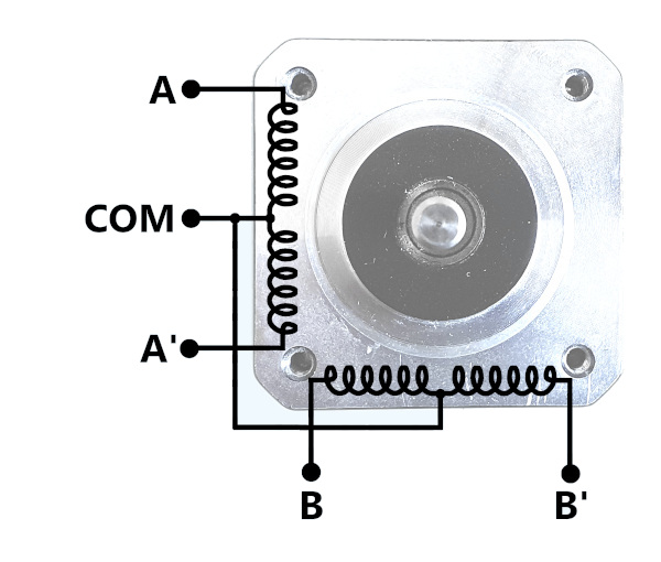
The Unipolar Stepper Motors have five wires. They operate with one winding with a center tap per phase. The common wire (COM) is permanently connected to the ground (most often). We can reverse the magnetic field by supplying connectors A or A’ (B or B’).
Thanks to this design, four transistors (not eight as in bipolar steppers) are enough to control this motor.
But because we can only use half of the coil in each phase, these steppers have relatively low torque.
Bipolar or Unipolar stepper motor
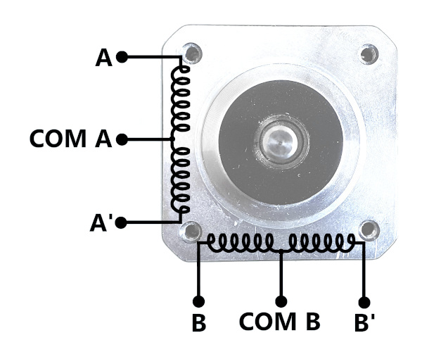
This type of Stepper Motors has six wires. As you can see in the picture it is a combination of unipolar and bipolar motors. It has two windings, separated from each other, but they are divided in half and brought out in the form of two additional wires. This solution allows you to control in both ways. It is up to you whether you prefer more torque or simpler control.
What do I need to keep in mind when choosing a stepper motor?
Disadvantages
- the speed of stepper motors isn’t very impressive – from a few or a dozen revolutions per second
- as the speed increases, its holding torque (Nm) decreases
- relatively high power consumption
- high heat emission
- if the load is too high, missing steps may occur
Advantages
- high positioning accuracy, without any feedback
- ease of control – the number of pulses determines the position of the shaft, and the frequency determines the speed
- possibility of working at low speeds (no gears needed)
- the life of the stepper motors is quite long, thanks to the lack of friction elements
Summary
I haven’t covered all types of Stepper Motors in this article. But there are so many, I could write a book. And I assume that you are here because you just wanted to find out how these motors work. Therefore, I focused only on the most popular types that you can meet on a daily basis.
I hope you’ll find this knowledge useful when you choose a stepper motor for your next project 🙂
Related Articles
How Triac works? – The Complete Illustrated Guide
Triac is a semiconductor component that you can treat as…
How to program STM32 – The Complete Guide
In this article, I’m gonna show you how to program…
How to control AC voltage with a microcontroller?
To control AC Voltage (usually AC Mains) with a microcontroller,…