

Personally, I’m a fan of centralized “smart” systems. Thanks to this, I have all the logic and executive devices in one place at home.
In this article, I introduce you to such a central device: the Smart Home HUB. The project is completely OPEN-SOURCE, so you can download all files and edit whatever you want.
I also created a Facebook group regarding this device. If you’ve any questions or ideas for improvement, you can do it right there.
Video version

General concept
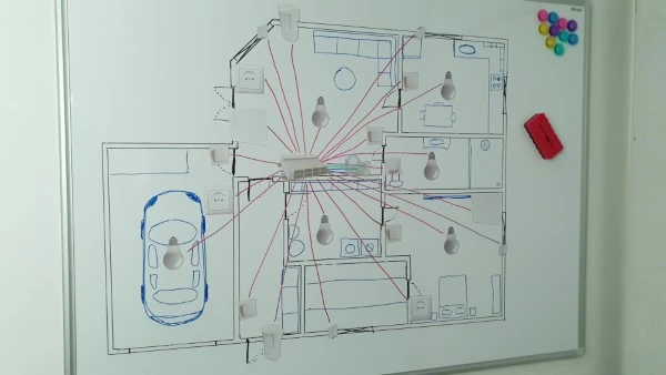
The HUB is the central part of my electrical installation. This is where almost all cables are linked. All binary sensors like wall switches, windows/doors, and presence detectors. And receivers powered with mains such as lights, outlets, and thermal actuators are joined here. Additionally, it’s connected to a Smart System (in my case, the Home Assistant). So its capabilities increase immensely. Now, I have at my disposal all the nice features provided by the system itself. And I can use them to control all “smart” appliances in my house.
I’ve covered the entire design and assembly process in this video. Including the disassembly of the previous version of the HUB.
Source files
The project is totally open-source, which means you can grab it and tweak it however you please. You can snag my design, the PCB layout, the 3D model, the bill of materials, and firmware – and make it exactly as is. Or, you can use it as a jumping-off point, make changes, and whip up something totally fresh.
Where can I buy it?
If you don’t want to “play” with outsourcing the production of boards you can buy ready-made ones in my store.
Electronics
I created this project in Fusion 360. Both the electronic and mechanical parts. And since it’s open-source, next to the pdf with the schematic, you’re gonna find files from this program.
The device, depending on the needs, can consist of up to 8 modules. Additionally, each module consists of three PCBs. Of which the PCB responsible for the INPUT has two versions (RJ45 or spring terminals). That’s why there are so many of these files.
The sponsor of this project is JLCPCB. They made all these beautiful boards for this project. For a few bucks, and in a matter of days, you can have a professional PCB on your deck, ready to solder 🙂 And if you don’t feel up to it, they can solder all SMD components for you.
ESP32 POE

The main control unit of the HUB is ESP32 placed on the ESP32 POE module. I chose it because it’s small, available (which isn’t apparent these days), and it’s open-source. My key requirements were the Ethernet port and native integration with the Home Assistant via ESPHome. But of course, you can use Tasmota, ESPEasy, or whatever software you want.
The module may be powered over Ethernet (hence the POE), which is a nice feature to have. If your router or switch can power other devices via an Ethernet port, why not use it. It simplifies the assembly. After all, it’s one less cable you need to connect.
Additionally, this module is readily swappable. And even though I don’t expect any problems with it, I’ll have a backup board programmed and ready to use if this one ever fails.
I/O Expander – MCP23017
The ESP32 module has several pins that I could use to control SSRs and/or get information from binary sensors. However, I needed a lot more of them. And here the MCP23017 chip from Microchip turned out to be helpful.
Each chip increases the number of I/Os by sixteen. And a maximum of eight can be connected to one I2C bus. Which gives an extra 128 GPIOs.
The maximum number of these chips results from the possibility of assigning a unique I2C address. When the master (an ESP32 module) wants to communicate with a slave (an MCP23017 chip) on the bus, it sends a START condition followed by the appropriate I2C address. The START condition alerts all slaves on the bus when a new transaction starts. The slave with the specified I2C address acknowledges the master. All the other slaves ignore further traffic on the bus until the next START condition is detected.
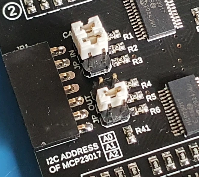
In order to change the address in MCP23017, you need to set the appropriate state on pins A0, A1 and A2. To simplify that, I’ve added jumpers on the PCB, which allows you to set a different one very quickly.
How to change the address of the MCP2317 chip

As you can find in the documentation in FIGURE 3-6 on the manufacturer’s website, the address register looks like this:
As you can see, this is an 8-bit register. But to make it more interesting, only 7 bits correspond to the address. The last byte indicates the direction of communication. The default address is 100000 – binary. That is 0x20 – hexadecimal. To change it, you have available three bits marked as A2, A1, and A0.
For example, if you change A0 to 1, you get 100001 or 0x21.
From now on, if you want to use this particular chip, you must use the address 0x21.
OPEN = 1 (TRUE), CLOSED = 0 (FALSE)
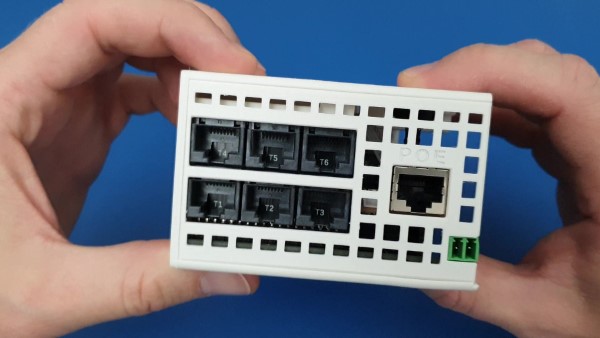
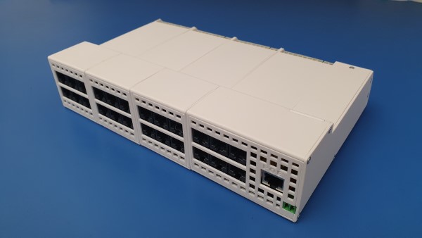
Inputs
Since in the previous version of the HUB, I used Ethernet connectors as input, here I’m gonna stick to the same concept. Each connector has 12V, GND, and 2/3 GPIs (General Purpose Inputs). Alternatively, you can use a more universal board with spring terminals.


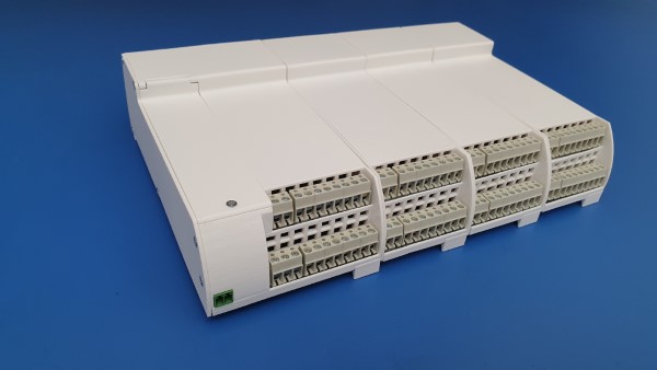
Outputs
These are the classic screw terminals you surely know, so there’s not much to talk about. However, let’s take a look at their arrangement.
As you know, a single module can have up to 16 outputs. I divided them into two parts with 8 channels each. Mainly to make the module as narrow as possible, but an additional advantage is the ability to connect different power sources. I mean, by this, that you can protect every 8 outputs with a separate fuse.
You can also power one of these segments via a UPS. Thanks to this, you’re gonna have 8 emergency outputs. For example, to power some critical lights or heating valves during a blackout.

Connector for expansion modules
The power section and the microcontroller are located on the main board, so I had to pass the supply voltage and the I2C bus to all PCBs. That’s what this connector is for. Both connectors are female, which may seem odd. But I did it deliberately. Thanks to that, connectors don’t stick out beyond the housing.
Therefore, to connect them, you need such male couplers.


Power supply
There are 3 voltage sections, and all of them may or may not be completely isolated from each other.
- 3.3 and 5VDC. For supplying logic.
- 12VDC for controlling SSRs and low-voltage home installation (for e.g. wall switches).
- Mains Voltage – For me, it’s 230VAC, but it could be 120V if you live in the US.
There are several configuration options here. Depending on your needs, the entire HUB can be powered from:
Option 1
You can use just one Mains cable. To 12V will be reduced by a switching AC-DC adapter. And then, it’ll be lowered to 5V with a (not present on my board) DC-DC converter.
In this option, low voltages are isolated from the Mains voltage by a transformer embedded in an AC-DC adapter. However, grounds of 12 and 5V are common, so there is no optoisolation here. But maybe it doesn’t have to be in your case.
Option 2
You can also connect the Mains voltage and use the AC-DC adapter to get the 12VDC. But the logic section you can supply separately. You can use an external 5V power supply or POE. Now all voltage sections are completely isolated from each other. That’s why I decided on this version of my HUB. It’ll make me sleep better.
Option 3
You can supply each section separately. In that case, you don’t need an AC-DC nor DC-DC adapter. This can be useful if you need more current in your low voltage installation than this adapter can provide. It gives 1.25A at 12V, which should be sufficient in most cases, but perhaps you have more demanding devices in your system.

Mains voltage detector
The HUB is able to detect a power failure thanks to a simple circuit with an optoisolator, a few resistors, and a capacitor. Of course, it can only do this if the logical part is supplied from a separate source. Preferably with UPS.
I wrote an entire article about detecting mains whit a microcontroller: How to detect mains voltage with a microcontroller?

Case
Of course, the casing is 99% 3D printed. The remaining 1% stands for a few M2.5 screws and a 3 mm rod.
In this article, I’ll focus on the main module as it’s more complex than expansion modules. If you manage to assemble that one, you’ll surely handle the next ones yourself 🙂
STEP 1
In addition to the printed elements, you’re gonna need: cyanoacrylate glue (Super Glue), pliers, and a screwdriver. Additionally a 3 mm rod, a few M2.5, and one M3 screw.
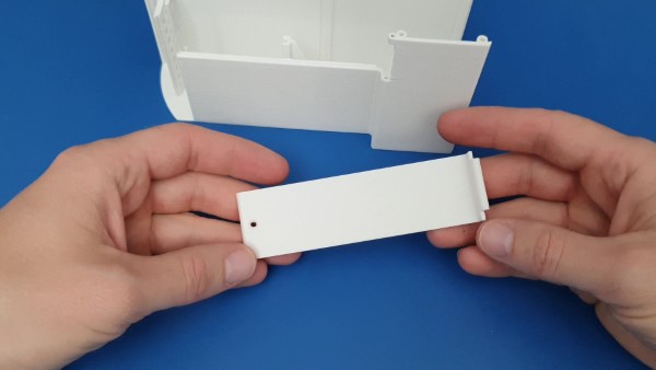
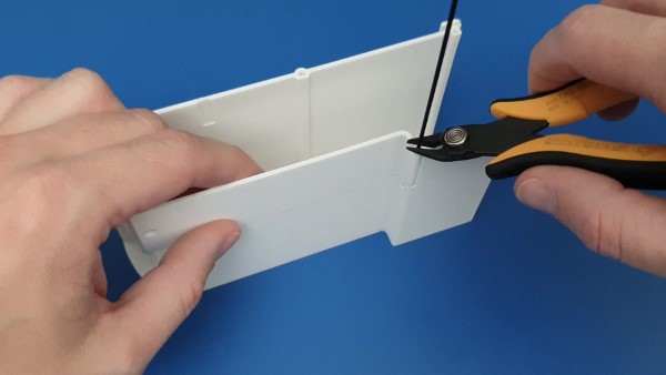
STEP 2
Put the flap in the slot. Push the rod into the hole and trim the excess so that nothing protrudes.
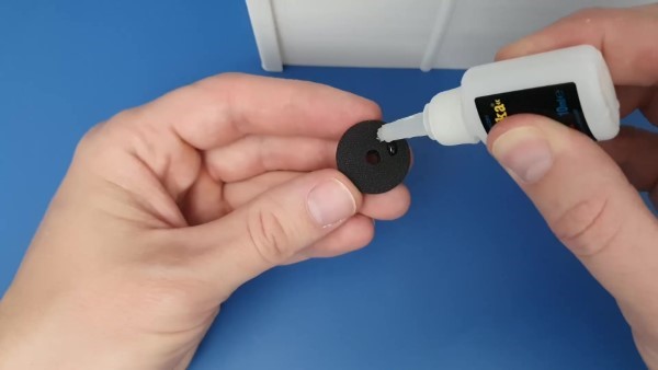
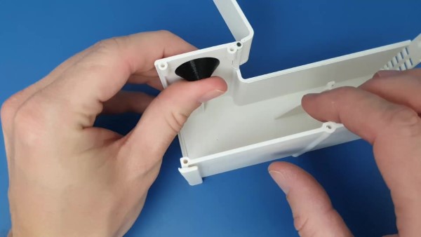
STEP 3
Stick the LED holder on the top of the housing. The exact place doesn’t matter. Do it wherever you want. As you can see, I did it in black color. Thanks to this, the LED is better directed, because the black filament is much less translucent.
STEP 4
Solder the LED on 5 cm cables. Cables for ICD connectors are perfect. And plug it into the JP2 connector.


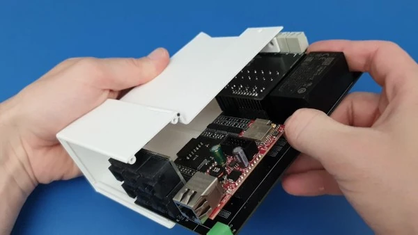
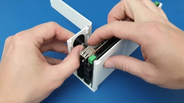
STEP 5
Slowly slide all electronics into the housing. Make sure that the board with SSRs and RJ45 connectors (or spring connectors) are in the appropriate slots. And then push the LED into place.
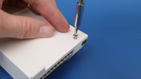
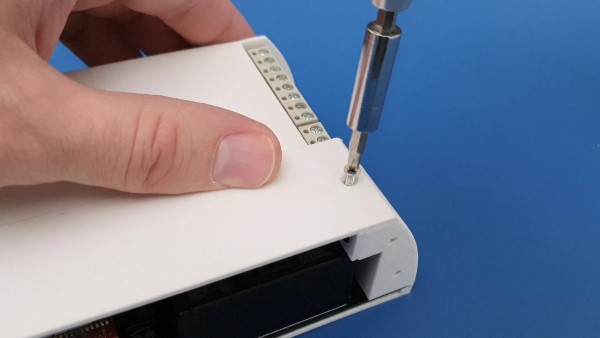
STEP 6
Attach the front of the case with a few screws. The one on the bottom (M3 x 10mm) is to hold the PCB in place. The rest of the screws keeps the entire housing together.
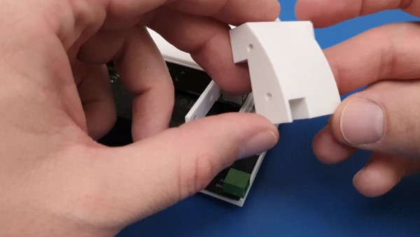

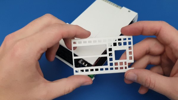
STEP 7
Insert the rear part of the housing. No screws or glue are needed.
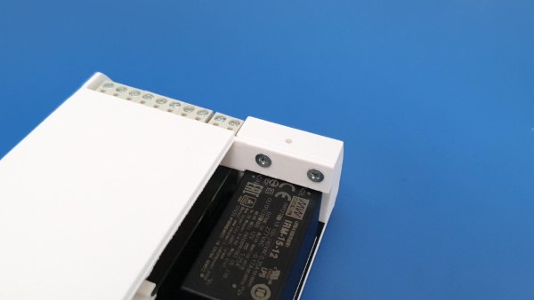
STEP 8
Screw on the side cover.
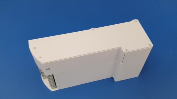

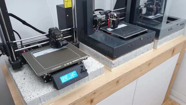
That’s it. The main module is ready. Now mount the expansion modules in a similar way. Depending on your needs, there can be from 0 to even 7. I need 3 modules. Ultimately it looks like this:
Firmware
For integration with Home Assistant, I used the best interface in my opinion: ESPHome. But of course, you can use whatever suits you best: eg Tasmota.
Programming the ESP32 POE module
Like any other module based on the ESP32 or ESP8266 chip, it must be programmed the first time using the UART-USB converter. Fortunately, the ESP32 POE module already has one on the board. So you don’t need extra hardware for this, except a micro usb cable.
However, before we get into programming, let’s prepare a configuration file in ESPHome.
ESPHome – configuration file
In volume, it’s the largest file I’ve ever managed to create. However, it is quite simple in its structure. Its size results from the number of Binary Sensors and Switches. Therefore, in this walkthrough, I’m gonna present you with just one block of each type.
Ethernet
To connect the HUB to a local network via an Ethernet cable, you need to start with this simple configuration. Nothing much to tell. Just copy this block and paste it into your file 🙂
ethernet:
  type: LAN8720
  mdc_pin: GPIO23
  mdio_pin: GPIO18
  clk_mode: GPIO17_OUT
  phy_addr: 0
  power_pin: GPIO12
RGB LED
In order for Home Assistant to know that this LED is GRB, you need to do two things:
- Configure which GPIOs are connected to the corresponding colors.
- Create Entity Light using these three predefined colors.
If you do, I also created 3 simple effects. Thanks to this, in the HA it’s enough to change the lighting mode to, eg. Fast Pulse, and the LED will start to flash.
output:
  - platform: ledc
    id: output_blue
    pin: 5
  - platform: ledc
    id: output_green
    pin: 14
  - platform: ledc
    id: output_red
    pin: 15

light:
  - platform: rgb
    name: "Status LED"
    red: output_red
    green: output_green
    blue: output_blue
    effects:
      - pulse:
          name: "Fast Pulse"
          transition_length: 0.5s
          update_interval: 0.5s
      - pulse:
          name: "Slow Pulse"
          transition_length: 1s
          update_interval: 1s
      - random:
          name: "Random Effect"
          transition_length: 1s
          update_interval: 2s
I2C
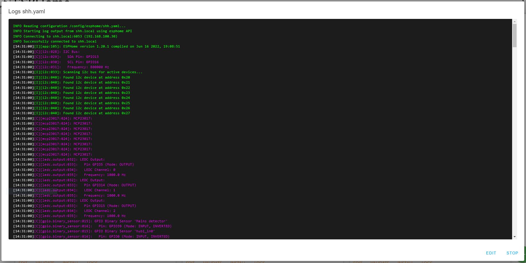
This is the important one. Without the I2C configuration, the ESP32 chip won’t be able to “get along” with the MCP23017 chips.
Command: scan checks all addresses that are detected on this I2C bus. You can use it to make sure that you set the correct addresses and that everything hardware-wise is properly connected.
i2c:
  sda: 13
  scl: 16
  scan: True
  frequency: 800kHz
MCP23017
This block of code will depend on how many and which modules you plan to use.
If you only use the main module, chips will always have the addresses 0x20 and 0x21. And it cannot be changed. In the expansion modules, you can set the address using jumpers. See chapter: How to change the address of the MCP2317 chip
mcp23017:
  - id: 'mcp23xxx_hub1_IN'
    address: 0x20
  - id: 'mcp23xxx_hub1_OUT'
    address: 0x21
  - id: 'mcp23xxx_hub2_IN'
    address: 0x22
  - id: 'mcp23xxx_hub2_OUT'
    address: 0x23
  - id: 'mcp23xxx_hub3_IN'
    address: 0x24
  - id: 'mcp23xxx_hub3_OUT'
    address: 0x25
  - id: 'mcp23xxx_hub4_IN'
    address: 0x26
  - id: 'mcp23xxx_hub4_OUT'
    address: 0x27
Binary Sensors – INPUTS
Here we determine that pin 0 on the chip with the address 0x20 (mcp23xxx_hub1_IN) will be the input. And we give it a name that will appear in HA.
  - platform: gpio
    name: "hub1_in0"
    pin:
      mcp23xxx: mcp23xxx_hub1_IN
      number: 0
      mode: INPUT
      inverted: True
    id: hub1_in0
Switch – OUTPUTS
This block is analogous to the previous one, except that we configure the output.
  - platform: gpio
    name: "hub1_out0"
    pin:
      mcp23xxx: mcp23xxx_hub1_OUT
      number: 0
      mode: OUTPUT
      inverted: False
    id: hub1_out0
Connection of Input to Output
If you want (like me) to omit the Home Assistant when turning on the light, you can do it very easily. In the block corresponding to a given light switch add: on_state: command.
I can turn on, turn off, or toggle it. Since I can also turn on the same light remotely with HA, it must be set: toggle.
  - platform: gpio
    name: "hub2_in0"
    pin:
      mcp23xxx: mcp23xxx_hub2_IN
      number: 0
      mode: INPUT
      inverted: True
    id: hub2_in0
    on_state:
      - switch.toggle: hub1_out11
That’s it for ESPHome configuration! Now, just generate the binary file from it and we can go to flashing.
Flashing ESP32
As I mentioned earlier, the first time it has to be done with a cable, every subsequent time you’ll be able to do Over The Air (OTA).
I use the ESPHome-Flasher for this. It is an open-source program and you can download it HERE.

After installation and launching, you will see a window like this.
Connect the ESP32 POE module. While inserting the USB, hold down the FLASH button. Your system will detect it as a COMx device.
Just select the correct COM number, navigate to the binary file and click FLASH ESP.
The rest will happen automatically.
After a while, your PCB will be programmed and ready to use. Combine it with the HUB if you haven’t aleready and see if everything works as it should.
Summary
Thanks for sticking to the end! Your Smart Home has gained quite a powerful device in its arsenal. Now, thanks to this HUB you can connect a whole bunch of binary sensors and control mains powered devices.
If you have any questions or suggestions, feel free to contact me at contact@smartsolutions4home.com
Related Articles

SS4H-ZRG Zigbee Rain Gauge – DIY project based Zigbee Door Sensor
In this article, I’m going to show you how to…

SS4H-SSR Smart Extension Board – DIY project based on ESP8266
With these kinds of projects, they are often created when…

SS4H-SD Smart Doorbell – DIY project based on ESP32
You surely know this feeling when the doorbell rings while…