
In this article, I’m going to show you how I built my own mechanical keyboard. Or rather a macro pad. If you want to be as productive as possible, this device is definitely for you.
I’m also going to make a step-by-step tutorial so you can do it yourself.
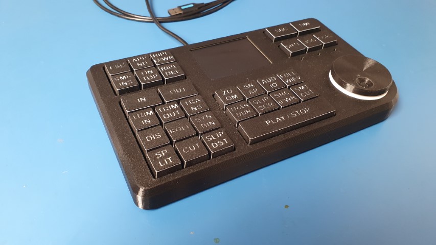
Disclaimer: I made a wooden case for it. But I realize that not everyone has a CNC at home. That’s why you can 3D print it instead. Functionally it’s exactly the same.
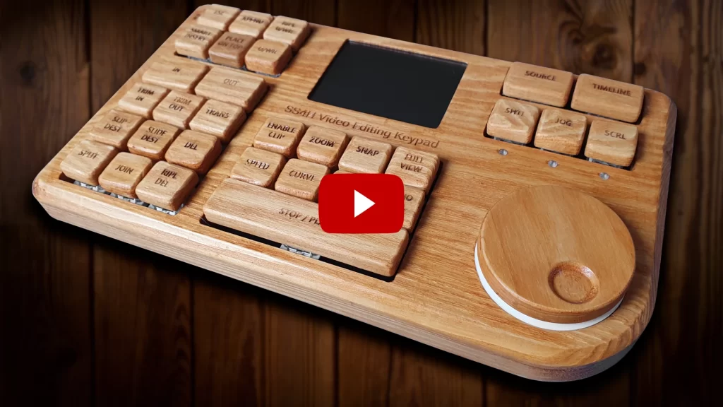
Video version
Source files
The project is fully open-source, so you can download and modify whatever you want. You can take my schematic, the layout of the PCB, the 3D model, BOM, Firmware and make this exact keypad. Or use it as a base, modify and create something new.
If you want to receive all of them put the email below – I’ll send a link to you straight away.
The firmware can be found on GitHub: LINK
Where can I buy it?
If you don’t feel like it or don’t have time to do it yourself, I invite you to my store. You can buy an unassembled PCB there.
What’s Macro Pad?
A macro pad is a device that allows you to assign to a single key any shortcut or action that would normally require a long sequence of keystrokes. It improves the efficiency of repetitive and tedious tasks by a lot.
You can think of it as a box of shortcuts. And you can freely modify them to suit your needs.
Electronics
The sponsor of this project is JLCPCB. They made all these beautiful boards for this project. For a few bucks, and in a matter of days, you can have a professional PCB on your deck, ready to solder 🙂 And if you don’t feel up to it, they can solder all SMD components for you.
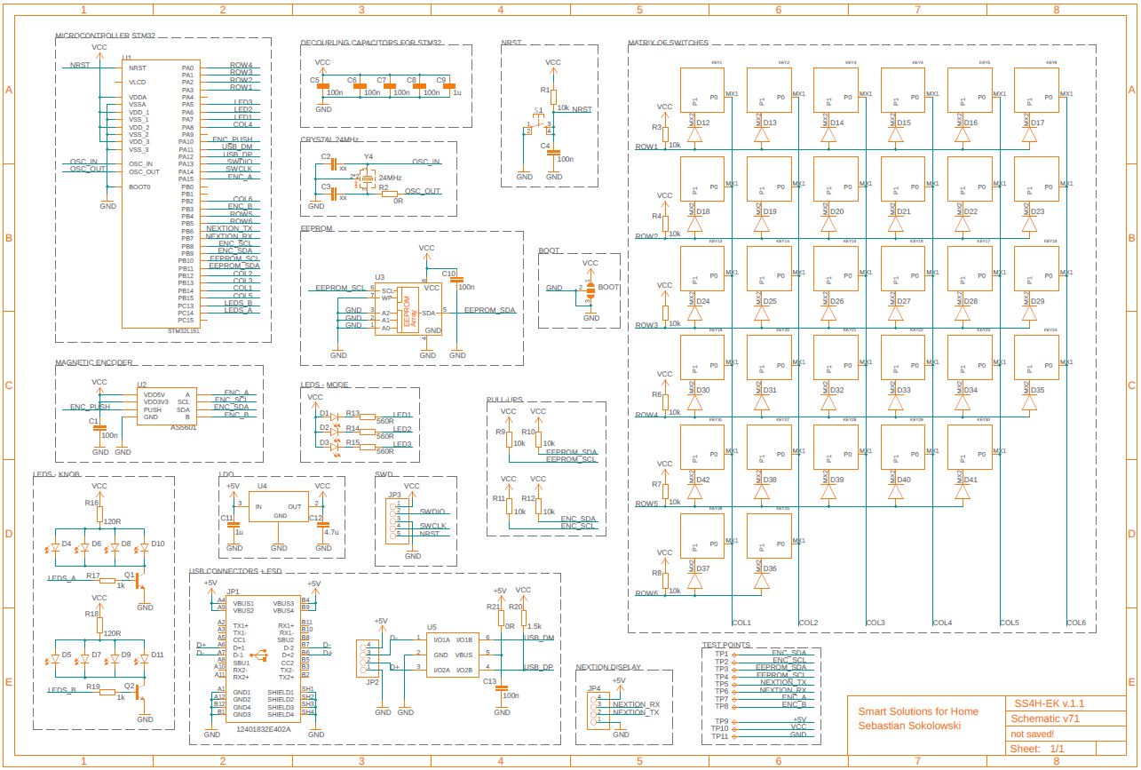
I started the project with the schematic. At this point, I determined that I want exactly 31 keys, a knob, and a display. I’m not gonna go deep into every element, but…
Schematic
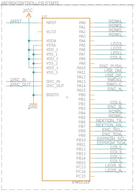
Microcontroller
The main brain of the device is the STM32L1.
Also, this model is quite popular and available on the market. Which is especially important now, during a global components shortage.
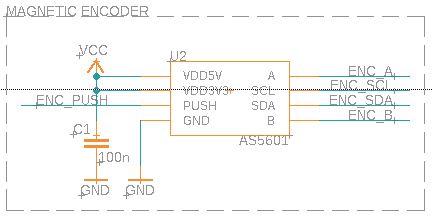
Knob
To read the position of the knob, I used a magnetic rotary encoder, which has a much longer life span than the classic, mechanical one. There are no physical contacts (no moving parts) in such, which wears out over time. And from the microcontroller standpoint, they work exactly the same.
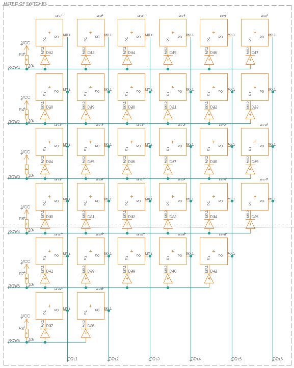
Keys
To connect 31 keys I needed only 12 GPIOs (6 inputs and 6 outputs). They are connected in a matrix fashion (like I guess in every commercial keyboard).
But how does the microcontroller know which key was pressed?
That’s a fantastic question! Fortunately, the answer isn’t complicated 🙂
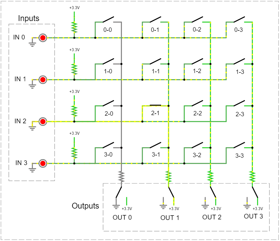
By default, all outputs (in our case – columns) are set to LOW. And all inputs (rows) are pulled-up by resistors. So they are detecting state – HIGH. Here represented by glowing LEDs.
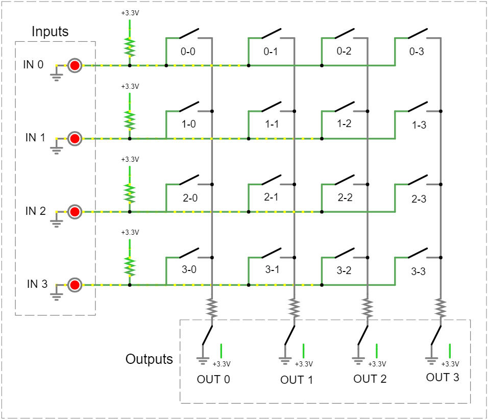
When a key is pressed (no. 2-1), it shortens column 1 with row 2. Now, input number 2 will detect the LOW state (the corresponding LED is off). It means that one of the keys in that row has been pressed, but which one? The same effect would be obtained by pressing the keys: 2-0, 2-1, 2-2, or 2-3.
In order to find out which key was pressed, we need to make a quick scan.
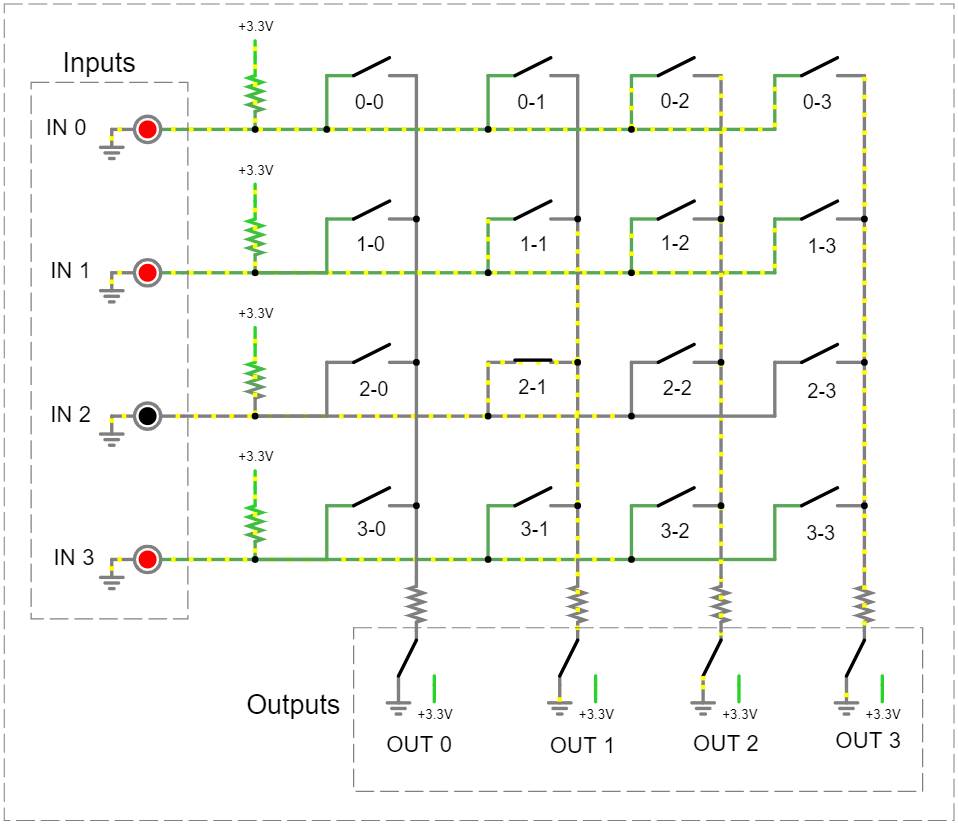
We perform the scan in a loop. The maximum number of steps depends on the number of columns.
In each step, we set to LOW on only one column. The rest of them should be HIGH. Now, we read again the current state. If it’s LOW we found that key. If not, we change the state of the columns and read it again. And we keep repeating this until the row goes LOW.
Step 1
Step 2

In our case, we already found the correct column in the second step. If we assumed that only one key could be pressed, we could stop at step 2.
What if we wanted to be able to detect several keys at once?
Unfortunately, a circuit like this won’t work in that case. What’s worse, pressing several keys in one row may (if you are really unlucky) damage the microcontroller.
Imagine we press, let say, the 1-0 and 1-2 keys. Since by default all columns are set to LOW, the row (input) will detect that something has been pressed and starts scanning. The first column remains low (GND level) and the rest of the columns become HIGH (VCC level).

And what just happened?
We actually just shorted VCC (OUT 2) and GND (OUT 0)! Not entirely, but for the sake of simplicity, let’s assume we did. And although the microcontroller is protected against something like that, it is definitely an uncomfortable situation for him. So let’s not do that.
To avoid this in the future, we can simply add diodes next to each switch. They act as guards, which prevents the current flow from VCC to GND. And now, the circuit will work properly even if we press all keys at the same time. Which is precisely what we were striving for.

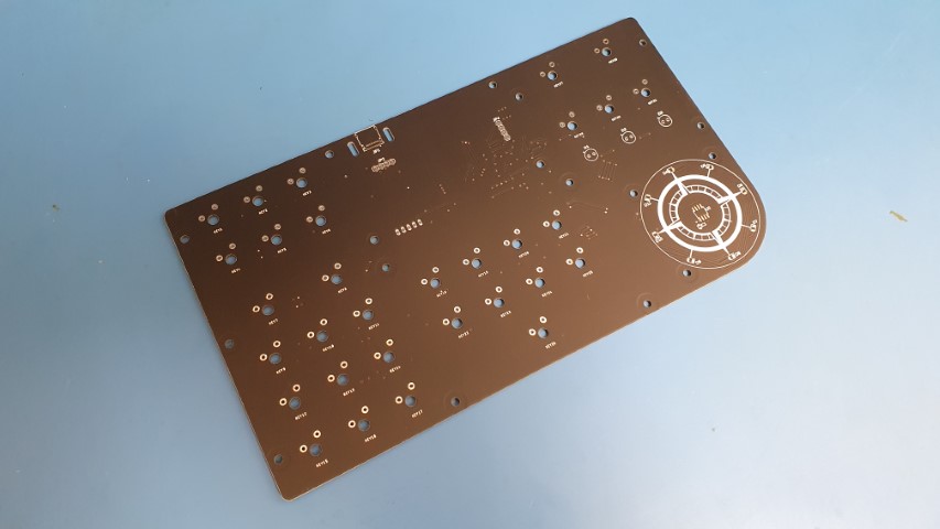
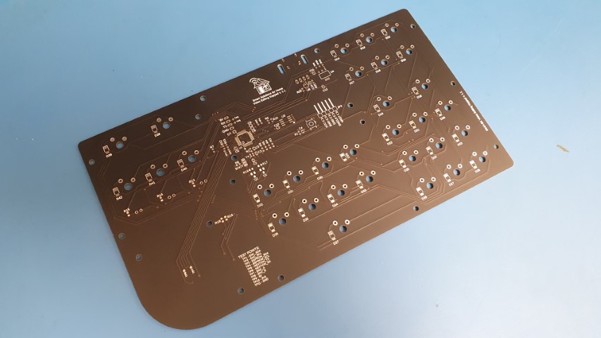
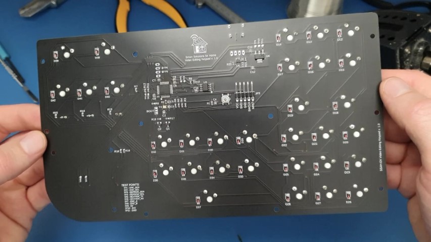
PCB
Now it’s time for the PCB. I usually want all my projects to be as compact as possible.
This time, however, I was more concerned with ergonomics than size. After all, a keyboard must be comfortable, so it cannot be too small. Thus, the size is close to 60% of the size of a classic keyboard.
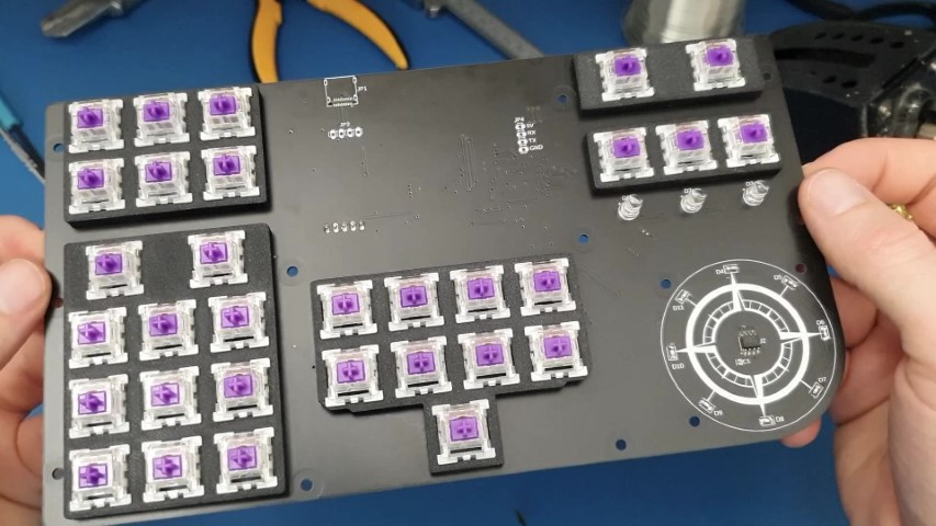
Soldering
Not much to comment on here. The thing is super simple. Start with SMD and then THT 🙂
Due to its dimensions (226×126 cm), the PCB didn’t fit on my heating plate.
The only thing I’d like to address is the key switch template. It’s not mandatory if the switches are soldered and not mounted in the socket. However, I recommend you use it. This makes it very easy to arrange them evenly on the PCB. In addition, it stiffens the entire device.
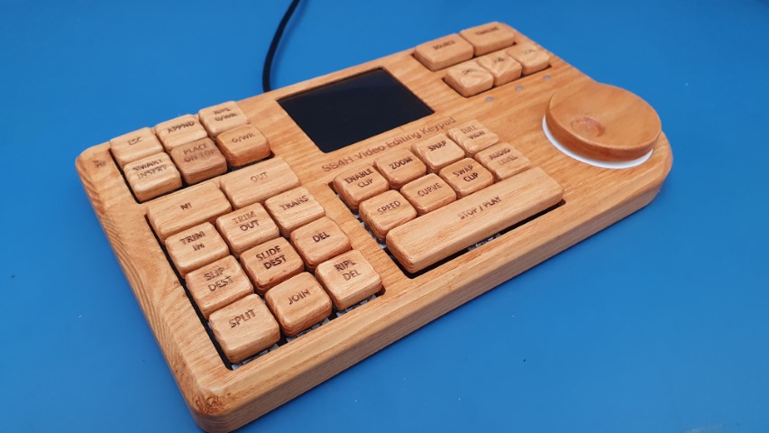
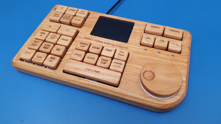
Case
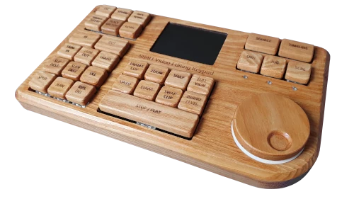
The enclosure is mainly made of wood. It wasn’t the easiest nor the fastest way, but it gives my keypad that premium vibe. So instead of additive manufacturing (3D printer), I used a subtractive one (a CNC milling machine).
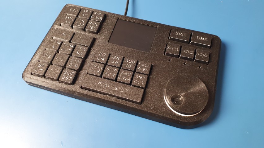
But of course, you can print it on a 3D printer. It’s gonna be simpler, cleaner, and (what’s most important) it’s gonna require much less post-production… sanding those f*** keycaps.. took forever.. 🙂
Wooden version
3D printed version
Legends
The next step was to make legends on these keycaps.
In printed keys, the matter is quite simple. To increase the visibility of the inscriptions, you can make them in two colors as I did.