
I discovered ESP8266 a few years ago. Since then, I’m fascinated by it. I use it wherever it fits 🙂 For less than $2, you can have a fully functional microcontroller with a full TCP/IP stack. It can run your device and be connected to a WIFI at the same time. It is the perfect solution for IoT applications and Smart Homes.
In this article, I will tell you how to program the ESP8266 chip, how to configure pins to put it into flash mode. You will learn how to connect a UART-USB adapter, and which type of module/board is best for you.
Let’s dive in right away!
What is ESP8266?
ESP8266 is a 32-bit microcontroller with a Tensilica processor, produced by Espressif Systems. It has sixteen configurable GPIOs, and build-in most of the popular interfaces like UART, SDIO, SPI, I2C, I2S, GPIO, ADC, PWM. It can run with a clock speed up to 160 MHz (default is 80 MHz). So you can use it like any other microcontroller to control your device. What makes it unique is self-contained Wi-Fi capabilities. It integrates antenna switches, RF balun, power amplifier, filters, and power management modules. All you have to do is add an antenna and some passive elements around, and you are ready to go!
You can also choose from a whole range of modules or boards witch ESP8266. They have all the necessary components onboard.
Which board to choose?
There are many modules/boards, and they are continually adding new ones. The current list you will find on Wikipedia. All these modules are based on the same ESP8266EX chip. They differ in shape, size, number of pins, type of antenna, and additional elements.
To somehow reasonably describe what you have to choose, I divided it into three levels. But don’t get me wrong – these aren’t levels of difficulty 🙂 Actually, it’s the opposite. Level 1 is the hardest one and Level 3 is the easiest.
Level 1 (lowest)
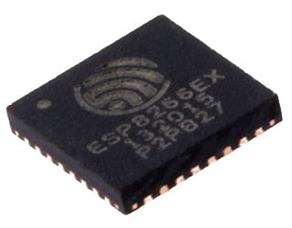
The lowest level is the ESP8266EX chip itself. If you are designing a hi-end device that must be as small as possible, or if you’ll produce it in large quantities and every penny is important, you should choose this one.
Of course, you have to do a lot of work in this solution yourself. Essential here is the ability to PCB design. For proper operation, several components around the chip are needed. Such as decoupling capacitors, resistors for pull-ups and pull-downs and antenna.
Speaking of which, if you designing the antenna yourself, then your device will not be FCC certified. If you need it, you can send it to the lab for testing. You will receive such a certificate if your device meets the requirements. For more details, visit the Federal Communications Commission website. If you need FCC certification then this is where you should start looking for information.
Keep in mind that it’s not cheap. It can cost up to $ 15,000. But if you plan to build your device, which will be sold in millions of pieces around the world, maybe it is worth it 🙂
Designing your own PCB with the ESP8266EX chip is a large and very interesting topic. That is why I will make a separate article about this.
Level 2 (middle)
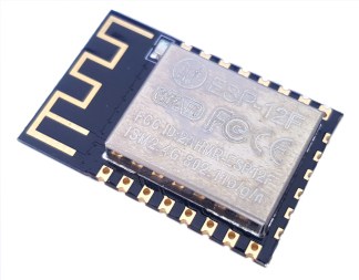
It is my favorite level, and I use it in most of my projects. These are modules with an EPS8266. They have all the necessary elements for proper operation, including the antenna! And most (but not all) are already FCP certified.
In this category, you have the most options to choose from. There are dozens of modules from different manufacturers. The most popular ones are probably from Ai-Thinker and Espressif itself.
Although there are a lot of elements on modules at this level, you have to take care of several things yourself.
- The modules don’t have a UART-USB adapter built into the board. And it is necessary to program the chip. I will write more about it in the chapter Connect ESP8266 to UART-USB adapter.
- You also need to ensure that the pins are in the right state. Eg. Pin Reset has to be HIGH during normal operation. More about functional pins in chapter Pinout.
- If you want to power the device with 5 V, you must also take care of the voltage regulator. Mostly you will use some simple LDOs.
LEVEL 3 (highest)
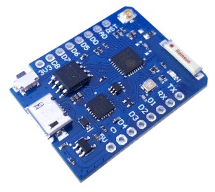
At this level, we are dealing with Evaluation Boards. Often they have modules from the Level 2 on board. These are the most complex solutions. In addition to basic components such as an antenna, capacitors, and resistors, they have a few extra things that simplify life:
- USB-UART adapter and convenient Micro / Mini USB socket for direct connection to a computer
- Voltage regulator, allowing connecting 5V directly to the board
- RESET and FLASH buttons
- Additional LEDs
They are compatible with the Breadboard. So you don’t have to solder anything.
This is a perfect solution if you are just starting your adventure witch ESP8266 and want to learn how it works. I often use it at the very beginning of the project. It is irreplaceable for testing and checking ideas.
However, I never use these boards on “real” devices. I don’t recommend you do this either. Tangled cables (which will not be avoided in this case) have always been a major problem in my projects.
To sum up: for prototypes and learning, it is perfect for finished projects better use modules from Level 2.
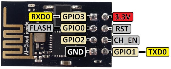
Pinout
From the previous chapter, you know that there is a great variety of boards and modules. So if you want to make a single switch, you will not use ESP-12F with a lot of GPIO. You’ll probably use a small module like ESP-01.
The important thing is the marking of the pins. Unfortunately, every producer has his vision on how to do it. Therefore, the markings may (and in most cases will) vary.
In this chapter, I will focus on some of the most popular boards. I will also show you the original pin names for the corresponding board/module.

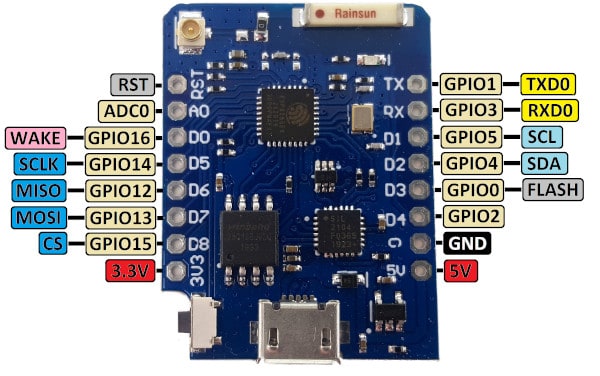
Description of all GPIOs
ESP8266EX has 17 GPIO pins, which you can assign to various functions. They can act as I2C, I2S, UART, PWM, and IR Remote Control, etc.
You can find more details in the documentation on Espressif website.
| PIN | Direction | Description |
|---|---|---|
| GPIO0 | INPUT / OUTPUT | GPIO0 is used to select booting mode. Pull it to GND during startup for flashing mode, pull to VCC (or leave it open) for normal boot mode. In most boards (level 3), it is connected to a flash button. If you use a module (level 2), it is convenient to design a button that shorts it to ground. In normal operation mode, it can be used as a classic GPIO. |
| GPIO1 | OUTPUT | GPIO1 is used as a UART0 TX during flash programming. On your PCB, connect it with the pins for the UART-USB adapter. In normal operation mode, it can be used as an output GPIO. It is HIGH at boot. If you pull it to GND during startup – boot fails. |
| GPIO2 | INPUT / OUTPUT | GPIO2 can be used as a classic GPIO. It is often connected to the LED. It is HIGH at boot. If you pull it to GND during startup – boot fails. |
| GPIO3 | INPUT | GPIO3 is used as a UART0 RX during flash programming. On your PCB, connect it with the pins for the UART-USB adapter. In normal operation mode, it can be used as an input GPIO. It is HIGH at boot. If you pull it to GND during startup – boot fails. |
| GPIO4 | INPUT / OUTPUT | GPIO4 often used as SDA for I2C (any other pin can be used as well). In normal operation mode, it can be used as a classic GPIO. |
| GPIO5 | INPUT / OUTPUT | GPIO4 often used as SCL for I2C (any other pin can be used as well). In normal operation mode, it can be used as a classic GPIO. |
| GPIO6 | Not recommended | GPIO6 is used to connect with the clock pin of the SD card. |
| GPIO7 | Not recommended | GPIO7 is used to connect with data pin 0 of the SD card. |
| GPIO8 | Not recommended | GPIO8 is used to connect with data pin 1 of the SD card. |
| GPIO9 | Not recommended | GPIO9 is used to connect with data pin 2 of the SD card. |
| GPIO10 | Not recommended | GPIO10 is used to connect with data pin 3 of the SD card. |
| GPIO11 | Not recommended | GPIO11 is used to connect with the command pin of the SD card. |
| GPIO12 | INPUT / OUTPUT | GPIO12 can be used as a MISO pin for the HSPI (High Speed Parallel Interface) interface. It can be a classic GPIO if you don’t use HSPI. |
| GPIO13 | INPUT / OUTPUT | GPIO13 can be used as a MOSI pin for the HSPI interface. It can be a classic GPIO if you don’t use HSPI. |
| GPIO14 | INPUT / OUTPUT | GPIO14 can be used as a CLK pin for the HSPI interface. It can be a classic GPIO if you don’t use HSPI. |
| GPIO15 | INPUT / OUTPUT | GPIO15 can be used as a CS pin for the HSPI interface. It can be a classic GPIO if you don’t use HSPI. It is LOW at boot. If you pull it to VCC during startup – boot fails. |
| GPIO16 | INPUT / OUTPUT | GPIO16 can be used to wake up from deep sleep, or as a classic GPIO. |
| ADC0 | INPUT | ADC0 (Analog to Digital Converter) is 10-bit precision analog input pin. |
| CH_EN | not applicable | Chip Enable pin: – if HIGH: chip works properly. – if LOW: small current consumed |
| RST | not applicable | External reset signal: – if HIGH: chip works properly. – if LOW: chip under reset |
Connect ESP8266 to UART-USB adapter
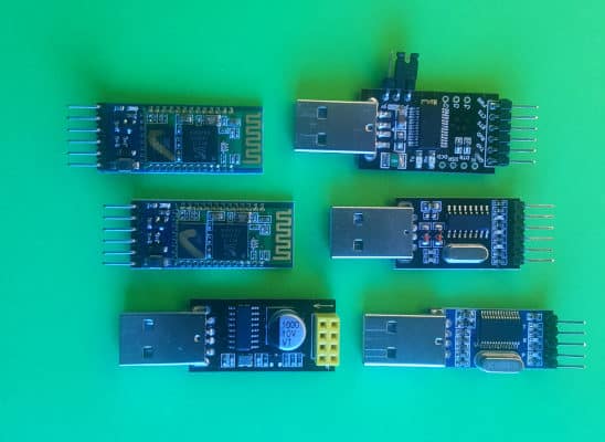
You can use any adapter. Even the cheapest one will do the job. It is important that it could work with 3.3 V. If you connect 5 V, you will fry the chip.
Connecting a module or board to the adapter is really easy. All you need is 4 wires. Connect them as follows:
- VCC -> VCC (3.3 V)
- GND -> GND
- RX -> TX
- TX -> RX
How to program ESP8266
The most universal and easiest way to program any ESP8266 chip:
- Connect the USB-UART adapter to ESP8266 as follows: VCC -> VCC, GND -> GND, RX -> TX and TX -> RX.
- Pull the GPIO0 pin to GND.
- Connect the adapter to the computer.
- Run a program for flashing via UART, e.g. ESPEasy.
- Select the appropriate COM port and binary file you want to upload.
- Press the Flash button.
- After success, reset ESP8266.
The above procedure is probably the most universal. You can program any ESP chips this way. It doesn’t matter what you used to generate the binary file. Use an environment that you know and like the most.
Some of them, like the Arduino IDE, have a built-in programmer. So you don’t have to use any other external program to flash the ESP8266 chip. Others like ESPHome can program OTA (Over the Air). We will follow these two ways below.
However, there are many more ways to generate a binary file. I counted 19 different environments! 🙂 It is impossible to describe all methods here. If you want to optimize your code in terms of size or speed, you can use C language, and one of the officially supported SDKs. On the other hand, if you prefer Python, Lua, Visual Basic or JavaScript nothing stands in the way 🙂
Programming the ESP8266 with the Arduino IDE
Arduino itself needs no introduction. It is an open-source hardware and software platform. And it is extremely popular among electronics hobbyists. No wonder, all their products are well polished and easy to use. But the biggest advantage is the community gathered around it. Thanks to them you can program the ESP8266 chip using the IDE.
- The first step is connecting the UAR-USB adapter to the ESP chip. I described how to do it in the chapter Connect ESP8266 to UART-USB adapter. Remember to pull GPIO0 to GND before connecting the USB.
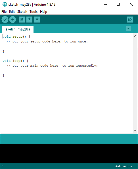
- Run Arduino IDE.
- Now we will just use the community work 🙂 Add to IDE support for modules and boards with ESP8266. Go to File -> Preferences
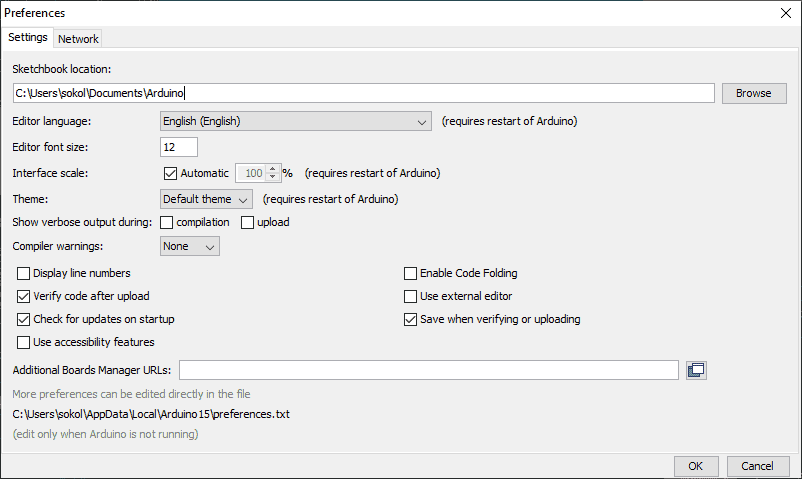
- Enter: https://arduino.esp8266.com/stable/package_esp8266com_index.json into the Additional Board Manager URLs field. If you want to add more boards, just separate the URLs with a comma.
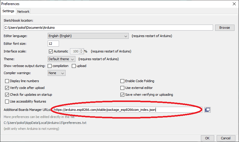
- Click OK. Now go to the Tools -> Board: “SOME NAME“ -> Boards Manager…
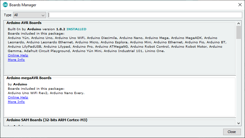
- Type “esp8266” in the field at the top or scroll all the way down. You will find there a package of libraries and examples for various ESP modules. Click Install
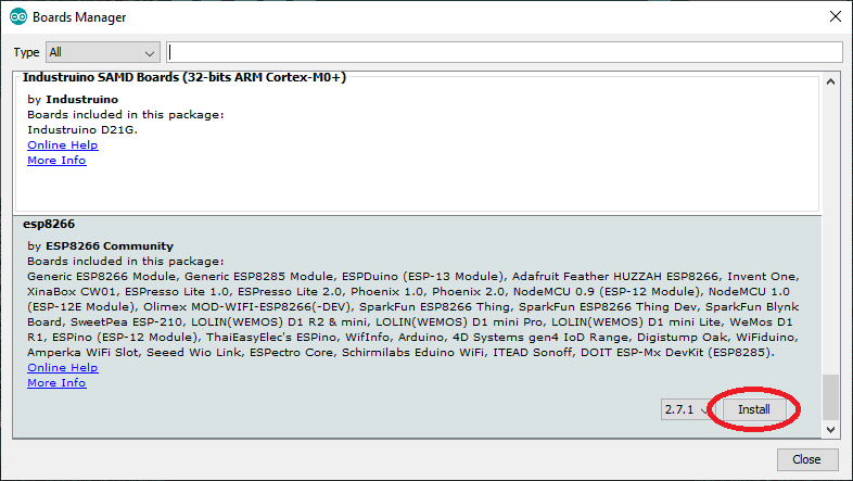
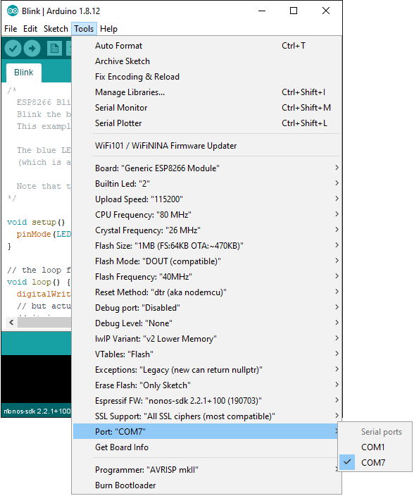
- Now you can go to Tools -> Board: “SOME NAME“, and select the board you are interested in. E.g., Generic ESP8255 Module.

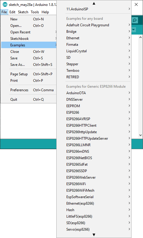
- Now you can write the code. But don’t worry, we won’t do it right now 🙂 At this point, you can use the ready sketch from anywhere. Often people share sketches on forums or Facebook groups. You can also use the examples you just installed.
To do this go to File -> Examples. And choose the one you want. I recommend Blink to start with.
- I assume you’ve already connected your module to the computer via the UART-USB adapter. You must select the correct port number. This number is assigned by the OS when you connect the device (adapter) for the first time.
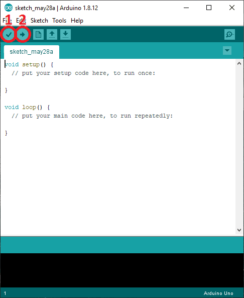
- There is only verification left and you can program chip ESP. Click Verify and then Upload.
- If everything went well, you should see the following window:
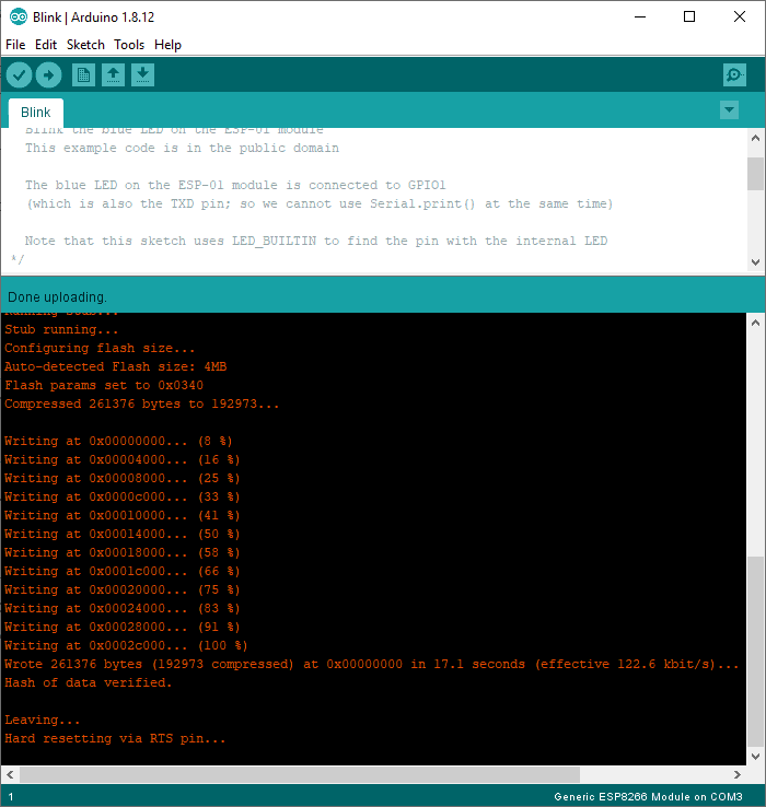
And that’s all 🙂 You just programmed ESP8266 using the Arduino IDE. Now all you have to do is reset the board and everything should work correctly.
Programming ESP8266 with ESPHome
If you’re using Home Assistant, ESPHome is the best firmware for any ESP modules. With it, you can generate a binary file, and then use the universal programming method (I described it above). Or (under certain conditions) use WIFI instead of the UART-USB adapter. It’s super convenient, especially if you don’t have easy access to the device.
I’ll describe both ways.
Adapter UART-USB
I assume that you have ESPHome installed and you have already added your device. If not, check out my article about Smart Garage Door Opener. In the Software chapter, I described how to do it.
For this example, I’ll use a configuration file from this project.
- After editing the configuration file, click SAVE and then CLOSE.

- Make sure you haven’t made any mistakes.

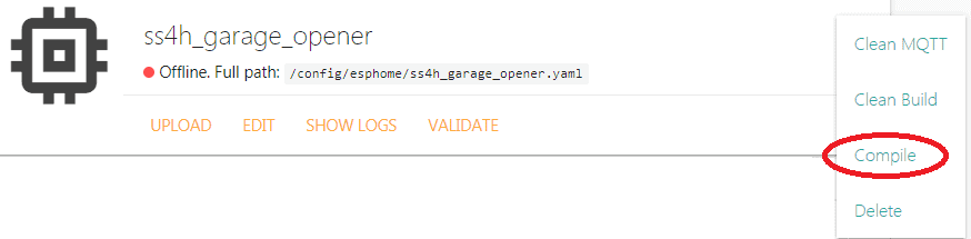
- Expand the menu (three dots) and click COMPILE.
- If everything went well you will see information about the compilation success. Click DOWNLOAD BINARY.
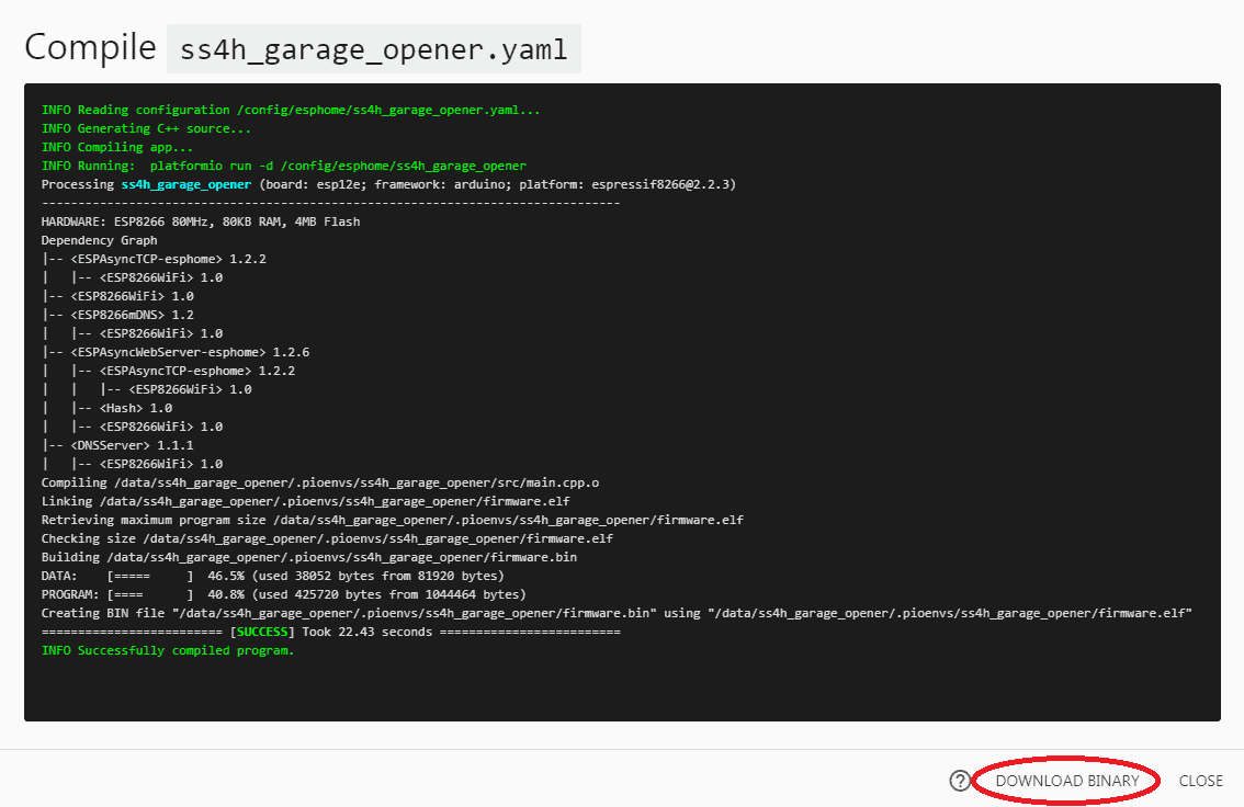
- Now you can use the ESP8266 universal flashing procedure, which I described at the beginning of this chapter.
OTA (Over The Air)
You cannot use this method when you flash ESP8266 for the first time. You have to start with the adapter method. The second limitation is the amount of FLASH memory. In older modules (e.g. ESP-01 – the blue one), there is only 512 kB, which isn’t enough. The minimum amount is 1 MB. Fortunately, currently produced modules usually have the required amount.
Programming in this way is super easy.
- When you finish editing the configuration file, click SAVE and then CLOSE
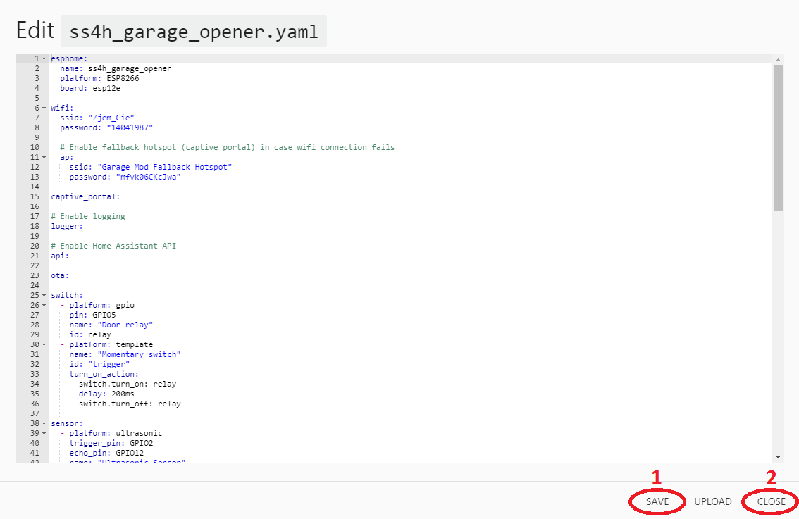
- Make sure there are no errors by clicking VALIDATE. If everything is ok you can click UPLOAD. The device should be Online. Otherwise, OTA will not work.

- After some time (if all went well) you will see a success message.

- That’s basically it. You have just updated the firmware on your ESP8266.
You can click UPLOAD from the editor. But I don’t recommend it. It is good practice to check for errors after each modification.
Summary
I see you got to the end. Congratulations!
In this article, you learned what ESP8266EX chip is, what is the difference between a module and an evaluation board, and how to program it. I showed you how to do it in a universal way that works with every module, or using the Arduino IDE and ESPHome.
And which ways do you use? Do you prefer Arduino, ESPHome, or something else?
Related Articles
How to detect mains voltage with a microcontroller?
The easiest way to detect mains electricity using a microcontroller is…
How to select a microcontroller?
Choosing the right microcontroller for the application is not an…
How to control AC voltage with a microcontroller?
To control AC Voltage (usually AC Mains) with a microcontroller,…