
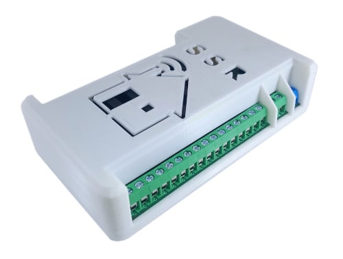
With these kinds of projects, they are often created when needed. In this case, it was completely different. I have been using something similar for a long time in my Smart Home system. And it works great! So I thought about sharing it with a broader audience. I made improvements in the schematic, designed a new PCB, a new case, and here it is – SS4H-SSR. It is an expansion board with sixteen SSRs and ESP8266 module.
In this article, you will learn how to make it yourself. You will receive all the source files and the necessary documentation. For you I left the most pleasant part, creating it 🙂
Introduction
Modules with SSR are very popular, especially among home automation enthusiasts. I can’t imagine Smart Home without relays. It is thanks to them that everything at home comes alive when it’s needed. It is the easiest way to control AC Mains, but not the only one. I described this and three other methods in detail in my other article: “How to control AC voltage with a microcontroller?”. I also recommend you my article about SSRs: “How SSR works“. You will find the details about how the Solid State Relay is built and how it works.
But similar boards already exist, why did you design another one?
Well, you’ll find out soon that SS4H-SSR has several additional features that make it stand out from the rest.
Main features of SS4H-SSR
SS4H-SSR is a pin extension with 16 semiconductor relays. However, it has several less obvious features:
- There is an ESP8266 module on board that allows you to control all channels via WIFI.
- It also has an MCP23017 chip that allows you to use the I2C communication protocol. Thanks to this, two wires + power supply are enough. It is a good solution when you have a board in the same place as the main HUB of your Smart Home (e.g. Raspberry PI).
- Alternatively, you can use MCP23S17 if you prefer SPI instead of I2C.
- You can connect up to 8 boards. All you have to do is change the address of MCP23x17 using DIPSwitch, and you can control 128 SSR independently with two wires.
- For diagnostic purposes, I built the AC Mains detection system. You can control if the high voltage reaches the board.
Hardware of SS4H-SSR
Ok let’s get started!
If you are reading this chapter, you are either planning to make this board yourself or are interested in technical details. In both cases, you need a schematic, PCB layout, 3D case model, configuration files, and shopping list.
If you want to receive all of this, just enter the email below – I will send a link to you straight away. If you entered your email on another project, you could use the same link that I sent you then.
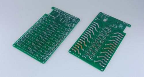
PCB
You will find GERBER files in the package you received from me. This is the standard format used by the PCB industry. It describes how the boards look. Each layer (copper, overlay, solder mask) is a separate Gerber file.
If you outsource it to someone, just them send these files, they will know what to do 🙂
The sponsor of this project is JLCPCB. They made the board for this project. For a few bucks, and in a matter of days, you can have a professional-looking PCB in your home. And if you don’t feel up to it, they can solder all SMD components for you.
However, if you want to do it yourself, I recommend the free tool: GERBV. It allows you to view all layers and also export them to “pdf”, “png” or simply to print it. If you’ve ever made PCBs yourself, I’m sure you know exactly what the next steps are.
3D printed case

In the world of 3D printing, the most popular format is STL. The housing I designed consists of two parts. It is very easy to print. No supports are needed.
Again, if you order this case at someone, just send him the files.
If you have a 3D printer, slice the model and let’s do it 🙂
HINT:
You will need four wood screws to assemble the housing. Screw M3 length 10-15 mm will be ok.
Shopping list
In the shopping list, I wrote the exact models that I used in this project. There is a chance that you will not get precisely these components. Of course, you can use a replacement. But, in this case, read the documentation very carefully, make sure that the footprint matches, and you will not damage the component e.g. by giving too high current.
Necessary additions
In addition to the SS4H-SSR board itself, you’ll need a few little things. If you’ve ever programmed ESP8266 before, it’s very possible that you already have it at home. However, if you do not have to get it somehow:
- USB-UART adapter
- four “dupont” wires
- power supply preferably 5V (but 12v and 24V can also will do)
Assembly of PCB
Soldering the components shouldn’t cause you any problems. I tried to make everything clear.
The main executive elements are the SSR G3MB 202P. These are big THT components so solder them last. If you would like to buy them, you can do it on Aliexpress.
However.. 🙂
- On the bottom side of the PCB, the paths for connecting the mains voltage are deliberately not covered by a solder mask. Put solder tin on them. Thanks to this, at high currents they will not heat up.
- In case you intend to use I2C, you don’t need to mount the ESP-12F module and several components around. It’s always 2 – 3 USD of savings 🙂 Link to Aliexpress.
- If you prefer to use SPI instead of I2C, then you have the option. All you have to do is assemble MCP23S17 instead of MCP23017. Footprint is compatible and all communication pins are lead out to make them convenient to use.
- If you intend to use only one SS4H-SSR board, you don’t need to assemble Dip-Switch SW1. The device address will then be 0x27. In the next chapter I explain how addressing is done in MCP23017.
Changing the I2C address of the MCP23017 chip
If you want to connect more than one board, you must ensure that each board has a different address. In I2C you can have a lot of devices connected to one bus. The way to distinguish each of them is “address”.
The master device always sends information to all slaves. The beginning of each message is the address. Only the device with the matching address will reply to this message. That is why it’s so important that all addresses are unique.
Microchip in his MCS23017 chip enabled changing the address with three pins.
To simplify the whole procedure for you, I’ve added a switch on the PCB, which allows you to set a different one very quickly.
Let’s change this address

As you can find in the documentation in FIGURE 3-6 on the manufacturer’s website, the address register looks like this:
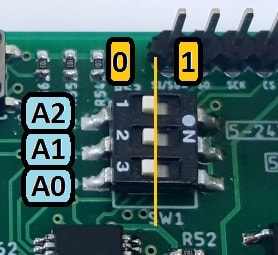
As you can see, this is an 8-bit register. But to make it more interesting, only 7 bits correspond to the address. The last byte indicates the direction of communication. The default address is 100000 – binary. That is 0x20 – hexadecimal. To change it, you have available three bits marked as A2, A1, and A0.
For example, if you change A0 to 1, you get 100001 or 0x21.
From now on, if you want to use this particular board, you must use the address 0x21.
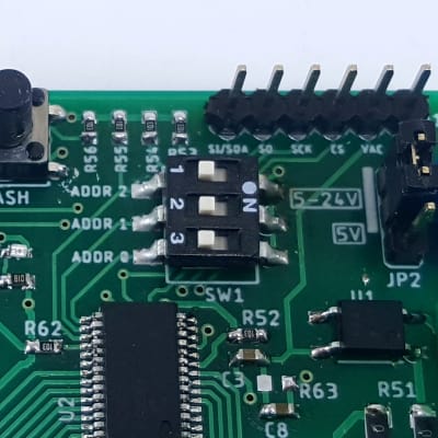
Connecting several boards to one bus
If you plan to use more than one board, you must (except for address change) connect the SDA, SCK, and GND pins together. You can use either a long pins or connect it with wires. It depends on how much space you have for it.
In this case, you need only one ESP-12F module or one Hub connection.
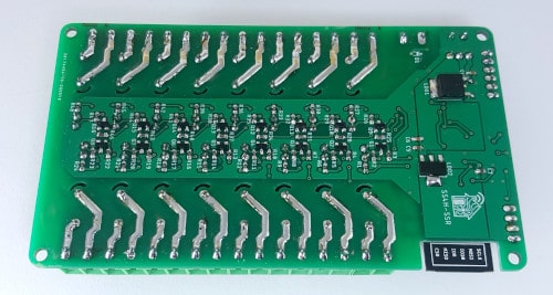
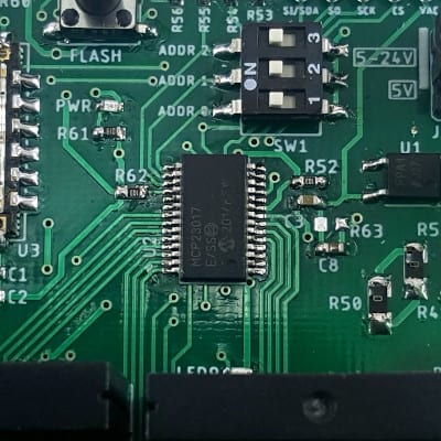
Ready PCB:


Detecting AC Mains
I placed the Mains voltage detection circuit in this project. You can monitor if voltage is present, and in case it wasn’t, e.g. send a notification. Or you can use it as a Zero Cross Detector In case you want to use an SSR without this built-in chip.
I wrote the entire article about detecting of Mains Voltage. I describe there in detail what it is, how it works, and how to make use of it.
Software of SS4H-SSR
In this chapter, we will integrate SS4H-SSR with Home Assistant. Of course, if you have Domoticz or OpenHAB, you can also use this board. Both support MQTT and I2C, or SPI. However, I am currently using HA (and I will probably use it for a long time), so in this article, I will focus on it.
Since SS4H-SSR can be connected wirelessly (via WIFI) or wired (I2C or SPI), I divided this chapter into two parts.
Wireless way
For ESP8266 modules (and ESP32), I like the ESPHome firmware the most. There is a great Home Assistant plugin that simplifies a lot configuration of a new device. If you don’t know ESPHome, go to the official website. There is a helpful step by step guide, which will explain how to install this plugin in your HA.
Adding a new device to ESPHome
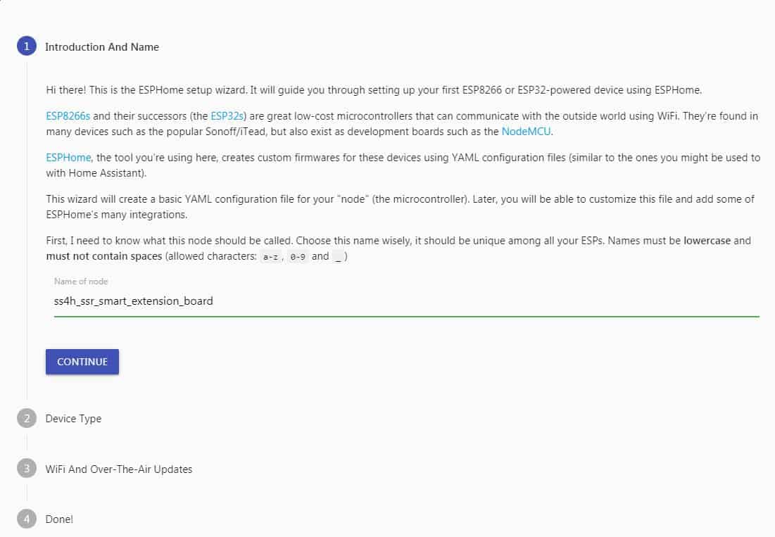
- Click the large green circle to enable the wizard that will guide you through the entire process.
- Enter the name of your device. This name must be unique for each device in Home Assistant. For me it will be “ss4h_ssr_smart_extension_board” – no funky characters! 🙂 Only “a-z”, “0-9” and “_” allowed.
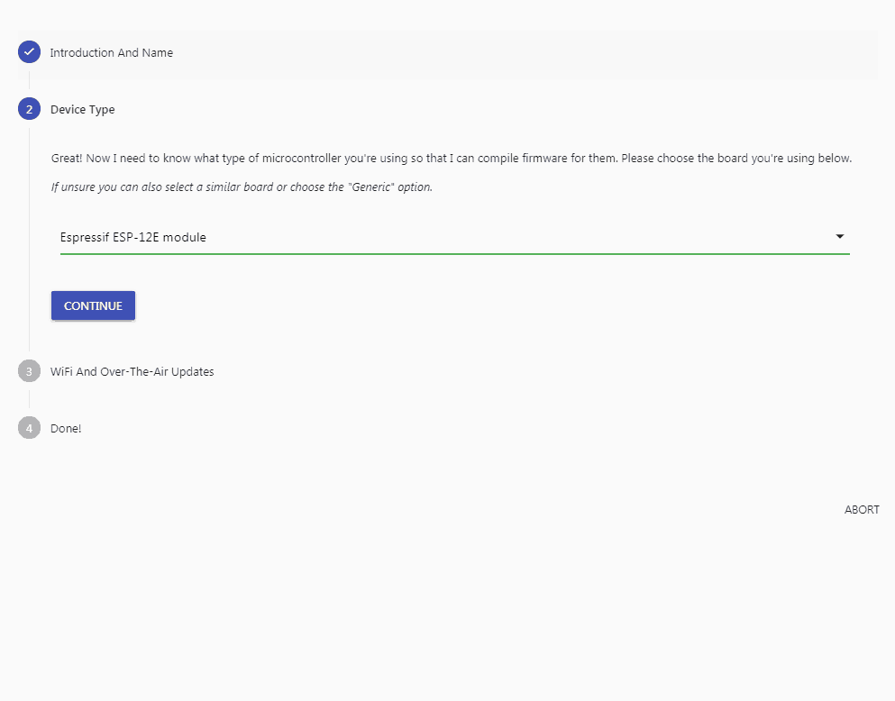
- Select devices from the list – “ESPRESSIF ESP-12E module”. In fact, this choice doesn’t really matter. ESPHome uses this only for mapping pin names. But, let’s choose the correct one for the sake of principle 🙂
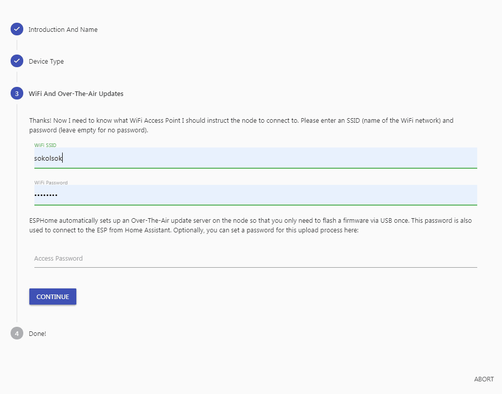
- Enter the SSID and PASSWORD of your WiFi network. You can leave “Access Password” blank.
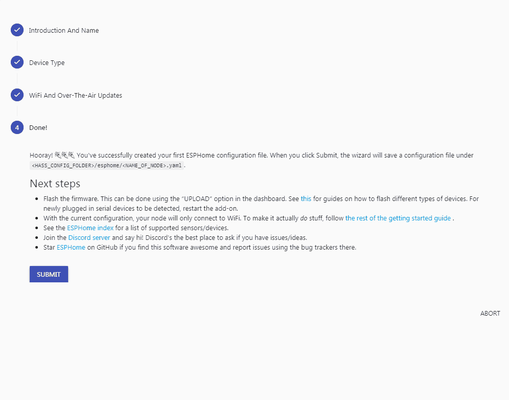
- Just click SUBMIT button on this page.
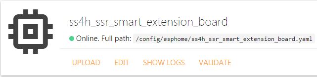
Now you should see the newly added device in the ESPHome main view.
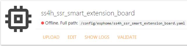
A red dot means that the device is added but not yet connected to a Home Assistant. Let’s make it green! 🙂
To do this, you need to reset the plugin. Just click: Supervisor -> ESPHome -> Restart. As soon as it turns on, reopen the web interface. ESPHome will generate a configuration template for your device.
Configuration ESP8266 module
Configuring ESP8266 to work with the MCP23017 chip is very simple. First, you need to add component i2c because that’s how they talk to each other 🙂 You don’t need to configure any pins. These defaults ones are appropriate (GPIO4 – SDA and GPIO – SCL).
Then you have to add sixteen times the configuration for each output. In the example below, I showed you how to do it for the first one.
i2c:

mcp23017
  - id: 'mcp23017_hub'
    address: 0x20

#individual SSRs
switch:
  - platform: gpio
    name: "Pin #0"
    pin:
      mcp23017: mcp23017_hub
      number: 0
      mode: OUTPUT
      inverted: False
Detecting AC Mains (optional) with ESP8266
You can check if the power supply is present. To do this, all you have to do is configure GPIO13 as INPUT. Every time the value of this pin changes, a message (MQTT) will be sent to Home Assistant. What you do with it’s entirely up to you. For example, you can prepare an automation or script that will send you a notification when there is some problem with AC Mains.
Of course, I am assuming that your Hub and Router are powered by some kind of UPS. If there will be a failure of the Mains and the Hub also shuts down, you will not receive any notification for sure 🙂
binary_sensor:
  - platform: gpio
    pin: GPIO13
    name: "Mains Detector"
Of course, I’m not going to make you write the whole config now 🙂 In the package with source files that you received is the entire configuration file. You can change the names if you want. The rest should rather remain unchanged.
Generating configuration file from ESPHome
If you are happy with the file, click “SAVE” then “CLOSE”. It is good practice to make sure that there are no errors. Just press “VALIDATE”. If you received a “thumb up”, it means it’s ok 🙂
Now you can generate the final binary file that will be upload to ESP8266. To do so, expand the menu (three dots icon) and click compile. It may take up to two minutes. The file download will start automatically after this.
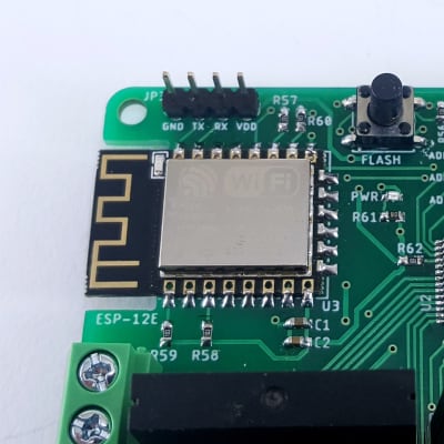
Connecting adapter with ESP8266

There are programming pins on the PCB: VCC, TX, RX, and GND. The USB-UART adapter has the same pins. Connect it as follows:
GND -> GND, VCC -> VCC (or 3,3V), RX -> TX and TX -> RX.
Be careful, don’t connect VCC to 5V – you will most likely kill the ESP chip!
Flashing ESP8266 module
Now you are ready to program the EPS8266 chip. You need any UART-USB adapter, four cables to connect, and a piece of software. I recommend ESPEasy. I use it for a long time, and it hasn’t disappointed me yet. You can download it here. But of course, you can use any program you prefer.
- Connect everything to your PC, but before you do this, press and hold the flash button. This way, you tell ESP that it will be programmed. If you don’t do this, the programming will fail.
- If you are using ESPEasy, go to the directory where it is located and copy your configuration file generated by ESPHome there.
- Now you need to figure out what number your computer gave the adapter. In Windows, turn on the “Device manager,“ and in the “Ports (COM and LPT)“ tab, you should find your device. On iOS… I don’t know 🙁 If you’re using Apple, you will find information for sure on how to do it.
- Once you know this number, turn on ESPEasy Flasher. From the “COM-Port” select the correct port, select your file from the “Firmware” drop-down list and then click the “Flash” button.
- If everything went as it should, after a while, you would see the message: “Flash Complete“.
Integration with Home Assistant
The first thing you should do after flashing is to reset your device. Simply turn the power off and on again. It is the best way to reset absolutely everything 🙂 After a few moments you should see in ESPHome that it is already online.
Home Assistant should automatically detect a new device.

Click “configure” and then follow Home Assistant instructions. You don’t have to change anything if you don’t want to. You can leave the default values.
Setting up Entity
Let’s prepare some interface now. It won’t be anything fancy and complicated. Just a simple switches that allow you to turn ON and OFF the relays.

- Go to Overview.
- Click Configure UI -> plus icon -> ENTITIES.
- You will see a graphic entity editor called: “Entities Card Configuration“.
- Start by giving the title, then add all SSRs.
- The drop-down list includes all devices (entities) that are integrated with your Home Assistant. Locate all that interest you.
Once you add all SSRs, it should look something like this:
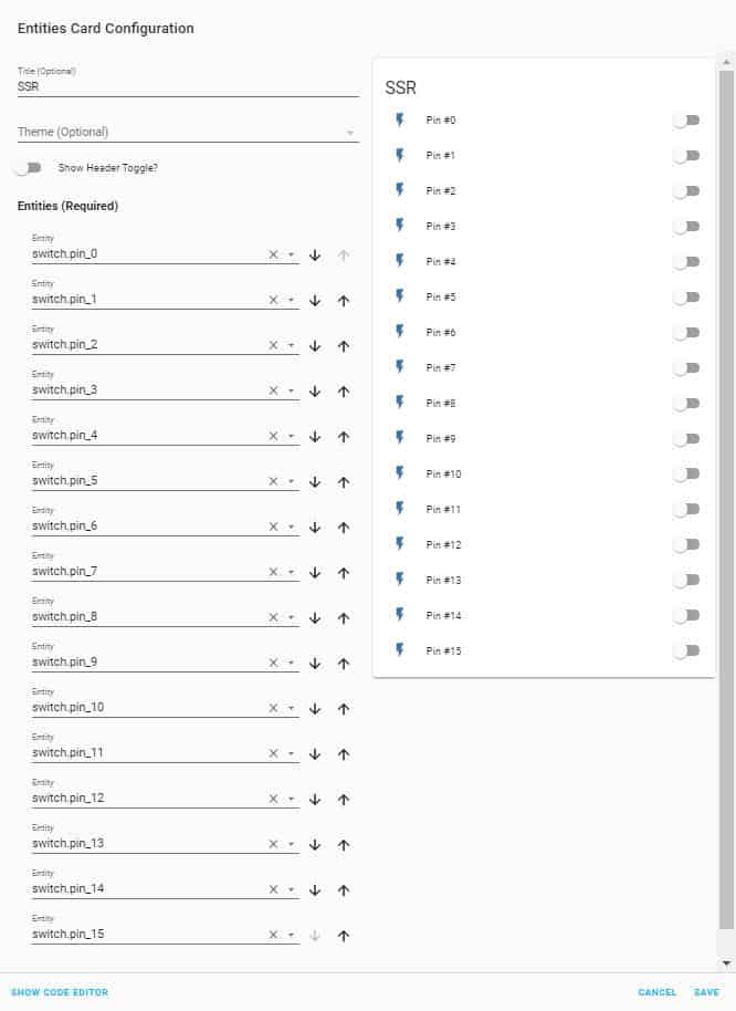
Congratulations! 🙂 You’ve just made a fully functional control panel. Of course, you can change the names and icons of any device. On the Home Assistant page you will find a detailed description of your options for changing the entity’s appearance.
But you don’t have to dig through all the documentation now. I will show you how to do it. Just the basics, but I think in most cases you won’t need more 🙂
Changing the appearances of Entity
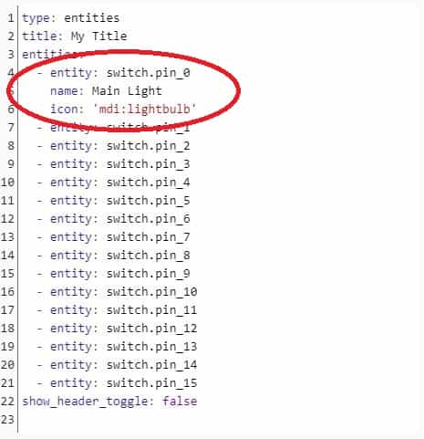
- Click SHOW CODE EDITOR.
- Add the “name” and “icon” commands to the entity that you want to change. You can find a list of all available icons on the Material Design Icons page.
Now pin_0 should look like this:

And that’s it! All you have to do now is install SS4H-SSR in the right place at home and connect all the lights or whatever you want 🙂
Wired way
In case your Hub located is in the same place where you want to have the relays, then there is no point in using WIFI, it is better to use I2C. It will be faster and more reliable. In this chapter I will show you how to connect Raspberry PI with SSh4-SSR Smart Extension Board with wires.
Connecting the SS4H-SSR to the Raspberry PI
To control the SSRs, you need three wires. If you also want to detect AC Mains, you need one more. In the photo below, I showed how to do it.
A detailed description of the pins in SS4H-SSR you can find on the schematic. In the case of Raspberry PI, I recommend you read the description on their official website – here 🙂


How to enable I2C in Raspberri PI
Home Assistant has an I2C bus disabled by default. So the first step will be to enable it. All you need is a USB Flash Drive.
Here’s what you need to do:

Step 1. Format it with FAT32/EXT4/NTFS and change name to “CONFIG”.

Step 2. In the root directory add a folder “modules”.

Step 3. Inside that folder add an empty file called “rpi-i2c.conf”. Just create a new file “.txt”, and then change the extension to “.conf”.

Step 4. Edit this file with notepad and add the following contents:
“i2c-bcm2708”
“i2c-dev”

Step 5. Go back to the root directory and add a file called “config.txt”.

Step 6. Edit this file with notepad and add the following contents:
“dtparam=i2c1=on”
“dtparam=i2c_arm=on”
Step 7. Insert USB Flash Drive into Raspberry PI.

Step 8. Click on “Import from USB”.
Step 9. After a few moments, reset the Home Assistant. I2C should now be up and running.
Integration with Home Assistant
Fortunately for us in Home Assistant, there is already ready integration with the MCP23017 chip. Integration will only take you a few minutes 🙂 You will find a description of this integration here.
All configuration (as usual) is done in the “configuration.yaml” file. I assume you know what is this and how to find it. Below is an example of how to configure the first three SSRs. Do the rest of the relays the same way.
switch:
  - platform: mcp23017
    i2c_addres: 0x29
    pins:
      0: pin 0
      1: pin 1
      2: pin 2
Detecting AC Mains (optional)
As with ESP8266 version, you can check if the power supply is present. Depending on which pin you used in Raspberry PI, you must configure it as INPUT. You can check the status of this pin manually. Or you can prepare some of the automation or script which for example, will send you notification of a problem in case of power failure.
binary_sensor:
  - platform: rpi_gpio
    ports
      20: Mains Detection
When you’re done editing “configuration.yaml”, remember to verify that there are no errors. Go to “CONFIGURATION” -> “SERVER CONTROLS” and click “CHECK CONFIGURATION“. If everything is correct, reset Home Assistant.
Wait a moment until the system reboots and then you can proceed to the next chapter.
Setting up Entity
The entity configuration is basically the same as for ESP8266. Go to Entity Configuration.
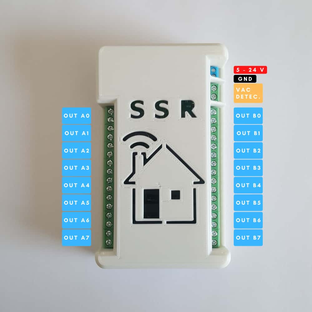
The MCP23017 chip has sixteen pins divided into two registers: A nad B. In the figure below, I marked them according to the documentation. When you configure this board in ESP826, or Raspberry PI pins have a number from 0 to 15. So pin A0 has the number 0, B0 – 8, B1 – 9 and so on and so forth.
If you want to use AC Mains detection, connect it to a terminal called VAC DETEC. This is an alternating voltage, so “polarization” doesn’t matter.
The supply voltage should be 5 V. However, there is an additional LDO (Low Drop Regulator) on the PCB that allows you to connect a higher voltage. But I don’t recommend doing that. In case all SSRs are switched-ON through regulator flows about 300 mA. This produces a lot of heat. You can do this only if you provide effective, external cooling for LDO. Otherwise, I highly recommend using an external 5 V power supply.
If you want to use more then 5 V, move jumper JP2 accordingly.
Typical application
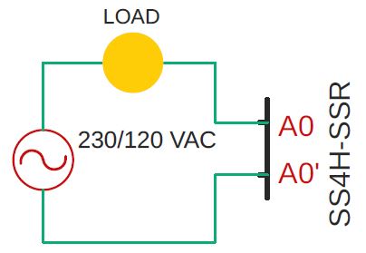
This is an example way to connect a load circuit to an SS4H-SSR board.
Note the type of power supply I have drawn on the schematic. It is an AC. And it’s crucial. If you connect the DC, it will not work correctly.
I wrote the entire article about Solid State Relays. You will learn from it why Alternating Current should be used in this type of SSRs.
How do I get this board?
As with my previous projects, and all subsequent ones, I made all source files available to you. So you can do it all yourself, which I encourage you to do. Nothing gives you greater satisfaction than creating something yourself 🙂
Related Atricles

SS4H-ZRG Zigbee Rain Gauge – DIY project based Zigbee Door Sensor
In this article, I’m going to show you how to make a Rain Gauge that…

SS4H-SHH Smart Home Hub based on ESP32 POE
Personally, I’m a fan of centralized “smart” systems. Thanks to this, I have all the…

SS4H-SD Smart Doorbell – DIY project based on ESP32
You surely know this feeling when the doorbell rings while you are doing something interesting:…