
You surely know this feeling when the doorbell rings while you are doing something interesting: watching a movie, playing a video game, or spending a romantic evening with your loved one. And when it turns out that this is an uninvited/unwanted guest, you get even more pissed off.
Of course, you can ignore it and not open the door, but there will always be this hint of uncertainty – “maybe it was important”.
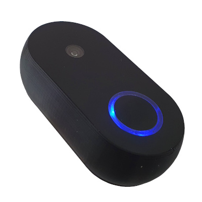
The solution to this problem is the “smart doorbell”. Thanks to it, you’ll know if it is worth getting up from the couch and opening the door or not.
In this article, we will make such a doorbell. I named it SS4H-SD Smart Doorbell. It was supposed to be “Video Doorbell”, but the short form sounds improperly 🙂
Introduction
There are many devices of this type on the market. Some of them can be integrated with popular HUBs such as Home Assistant, Domoticz, or OpenHAB. But in my opinion, they are too expensive. Besides, I love DIY solutions.
In this article, I’ll show you step by step how you can make the same smart doorbell yourself. I’ll share all the source files, so I’m sure you can handle it.
Main features
- Communication via WIFI
- Wide-angle camera
- Power supply in a wide range of 4.75 – 28 V
- Opening e.g. a gate (electromagnetic relay)
Video version

Hardware of smart doorbell
As with any other project, you can download all the source files such as schematic, PCB layout, 3D enclosure model, and config file. If you want to receive all of them, enter the email below – I will send a link to you straight away. If you entered your email on another project, you could use the same link that I sent you then.
PCB
The easiest way to make the PCB is to outsource it to a professional company. Just send them the GERBER files. They will know what to do with it. I suggest you use a black solder mask. Thanks to this, there will be fewer clearances from the front panel.
As you surely noticed, there are two separate bards: main-board and capacitive button. A capacitive button is nothing more than a piece of a flat conductor. So if you want, you can use any flat piece of metal and attach it to the pad. Keep in mind that the larger the surface area, the more sensitive the button will be.
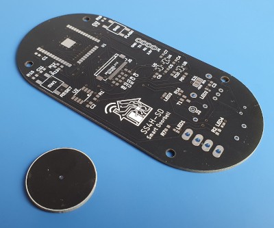
There is also space for a battery basket on the bottom side of the PCB. But as it turned out, battery operation isn’t the best idea in this case. It takes too long to wake up from Deep Sleep mode and connect to the network. It can work for temperature sensors but not for a doorbell.
The sponsor of this project is JLCPCB. They made the board for this project. For a few bucks, and in a matter of days, you can have a professional-looking PCB in your home. And if you don’t feel up to it, they can solder all SMD components for you.
Enclosure
The housing consists of three parts. The main and back parts are 3D printed. The front part, on the other hand, can be 3D printed or made of Plexi.
The backside has two holes for the power cables and the solenoid lock (if needed). Use pliers or break out the plastic to make a hole.
It is this part that should be mounted on the wall first. You will assembly the rest of the smart doorbell to it.

The central/main part has four PCB holders that won’t be printed without supports. That’s why I designed them myself. They work better for me than those generated by the slicer. You can download two versions, with and without supports.

I struggled with this element the most. But it was only my fault. I was trying too much.
As I mentioned earlier, you can print it on a 3D printer or use plexiglass. The first method is much simpler and less time-consuming. But it doesn’t look as neat as I’d like, and by “I” I mean “my fiancee” 🙂
Below I’ll describe how I made a plexiglass version.

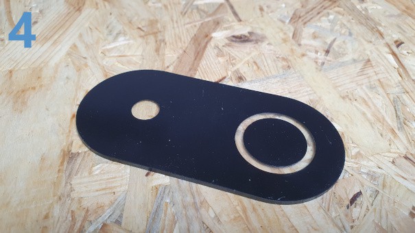
How to make a front panel from Plexi?
I cut the plexiglass shape on a CNC milling machine.
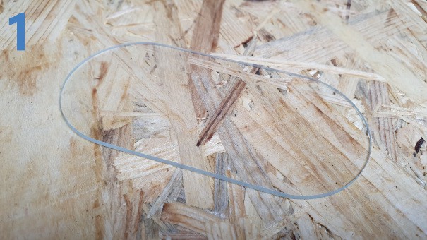
I put a round sticker on the place where the webcam will be.

I painted the whole thing with black spray.
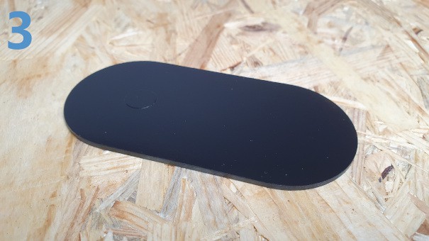
Finally, using the CNC again, I cut a circle to see the LED backlight.
Why didn’t I use a sticker like in the case of the camera window? I didn’t want this ring to be completely transparent. It was supposed to be milky, matte, and diffusing light. Of course, you can also make a mask here and then gently paint it with white paint. I tried this option, and it looks good. However, this method seems faster.
Necessary additions
No matter what firmware you’ll use, the ESP32 chip needs to be programmed. You need a UART-USB adapter. In most cases, you’ll only need it the first time. Each subsequent programming you can make over the air. Which simplifies the update procedure a lot. You probably already have something like this, and if you can’t use any. e.g. this one from Aliexpress.
You also need a power source. I use a fairly flexible DC-DC converter in the schematic therefore, the supply voltage range is wide, from 4.75 to 28 V. Max current is about 250mA. So probably every power supply nowadays will be more than enough.
Assembly of smart doorbell’s PCB
The assembly of components on PCBs is standard. The SMD elements are large (0603), so you can solder it without any problem.
Let me introduce you to some aspects that I think you should pay attention to:
ESP32 module
The ESP32 module can heat up during heavy loads, e.g. operating the camera, therefore it is important that the pad underneath is in good contact with the ground area.
It is best to solder it with Hot Air. However, if you don’t have this option, the thermal paste will also do the job.
Here you have a LINK to a proven seller on Aliexpress. But if you have another proven source, use yours.

Camera
The camera is in the FPC socket. So assembly it last once you’ve soldered everything. You can additionally stick it to the ESP module with double-sided tape.
I bought my camera here: LINK

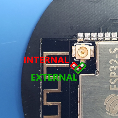
External antena
The ESP32-S module, in addition to the PCB antenna, has an SMA socket, so you can hook up an external antenna. If you want to increase the range of Smart Doorbell, this is the best method.
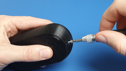
You need to resolder the resistor next to the socket. Additionally, you need to drill a hole in the housing to expose the antenna.
Capacitive touch button
The touch button detects the change in capacity. It is enough to close something that has a capacity (e.g. a finger) and the ESP32 chip will detect it. The larger the capacity and the closer the better. In our case, there is a 2 mm plexiglass between the button and the finger.
It definitely influences the sensitivity of the button, but luckily it seems to be sufficient to work properly.

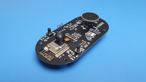
Ready PCB should look like this

Software for operating the smart Doorbell
Let’s take care of the software now. We’ll use ESPHome. However, if you prefer any other software that won’t be a problem either. The device is based on the ESP32 chip, so you can use Tasmota or ESP Easy if you want.
I am a big fan of ESPHome and Home Assistant myself. Therefore, it is in this chapter that I’ll describe integration with it.
ESPHome
At this point, I assume you have ESPHome installed, and you know how to add a new device. Just in case – I have covered it in detail in THIS article. Go straight to the “Software” part.
In this paragraph, we’ll now focus on preparing the configuration file.
There are two approaches in ESPHome:
- You can program basic switches and sensors, and all the automation you can do in the Home Assistant (frontend).
- You can do some of the automation directly in ESP (backend).
The second way is better. Because there are no delays on the ESP-> Hub-> ESP route, and it will work even if something bad happened to the WIFI.
Configuration file
You can download the entire file together with the rest of the source files. That’s why I’ll not describe it here to a T. I’ll tell you only about the most interesting parts.
Camera
The camera is an essential element of every Smart Doorbell. There are three parameters you should pay special attention to.
idle framerate – how many frames will be captured in idle mode. You can keep this value low, as not to fill the WIFI with unnecessary data. The default value is 0.1 fps.
max_framerate – If the client requests full speed it will get this value. You can set up to 60 fps, but the camera will get very hot. Keep this in mind. The default is 10 fps.
resolution – As the name suggests, here you set the resolution of the captured frames. The larger the value, the more memory is required. That’s why I put an additional 64Mbit PSRAM on the board. If you need a resolution greater than 800×600 then you must use it.
esp32_camera:
name: DoorCam
external_clock:
pin: 0
frequency: 20MHz
i2c_pins:
sda: 26
scl: 27
data_pins: [5, 18, 19, 21, 36, 39, 34, 35]
vsync_pin: 25
href_pin: 23
pixel_clock_pin: 22
power_down_pin: 13
vertical_flip: false
idle_framerate: 0.2 fps
max_framerate: 10 fps
resolution: 800×600
Touch button
Certainly, the most interesting parameter, in this case, is the threshold. Defines the value below which the ESP32 chip considers the button as a “touched”. It depends on many factors: the size of a button, distance from the finger, obstacle material, and even air humidity. You have to choose this value experimentally.
But don’t worry it’s very simple, and I’ll tell you about it for a moment.
script.execute: led_pattern1 – It’s just a simple script that flashes LEDs to give the user the visual feedback that a button has been pressed. If you put it under the on_press command, it will be performed immediately after touching the button. Alternatively, it could be called by Home Assistant, but then it would be delays depending on the quality of the network.
binary_sensor:
– platform: esp32_touch
name: “Doorbell Button”
pin: 33
threshold: 1100
on_press:
– script.execute: led_pattern1
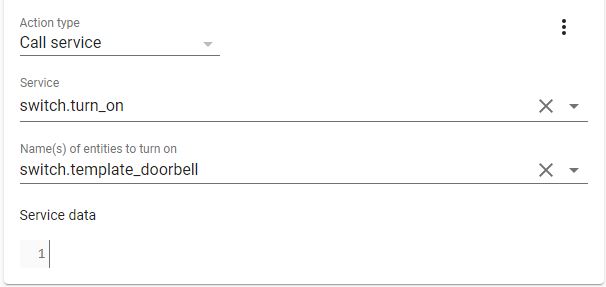
Switch
This part of the code is responsible for activating the relay and switching it off after 6s. Switch template_doorbel is visible as an entity in Home Assistant. We’ll use it later in automation to open the Solenoid Lock, assuming the person you see on the camera is welcome in your home 🙂
led_pattern2 – as you can already guess, it turns on a different LED blinking pattern, to let you know that the lock is open.
hint:
It doesn’t have to be a Solenoid Lock. You can connect whatever you want to this relay and control it as you like. Maybe you want extra light to illuminate the person in front of the door? Or some kind of electric repellent for uninvited guests? No problem!
switch:
– platform: gpio
pin: 4
name: “Doorbell Relay”
id: doorbell_relay
– platform: template
name: “Template Doorbell”
turn_on_action:
– script.execute: led_pattern2
– switch.turn_on: doorbell_relay
– delay: 6s
– switch.turn_off: doorbell_relay
Scripts
Here I describe which LED should turn on and after what time it should turn off.
If you would like to take advantage of the fact that ESPHome can insert c++, and write it in a more professional-looking way. Using variables and loops. I don’t recommend it. An insert of c++ is blocking. This means that nothing is done at the same time. It is very easy to break communication with Home Assistant this way. The ESP chip stops responding for a moment.
Writing a script the way I did works asynchronously. So no matter how long, it won’t interfere with the rest of the program.
script:
– id: led_pattern1
then:
– switch.turn_off: led1
– switch.turn_off: led2
– delay: 500ms
– switch.turn_on: led1
– delay: 500ms
– switch.toggle: led1
– switch.toggle: led2
and so on….
Calibrating the capacitive button in the ESPHome
Add temporarily something to the configuration file. Thanks to it, every ~0.5 s in a LOG you will get the current value of the capacity measured by the ESP32 chip.
esp32_touch:
setup_mode: True
It will look something like that:

You can clearly see when I pressed my finger. The greater the values between the pressed and non-pressed state, the better. Then there is less chance that a false touch will be detected.
Unfortunately, in case I didn’t touch the button directly. I put a nice locking plexiglass in between. Therefore the values aren’t very different. But in my experience, it is enough.
In your case, these values may be different. For the threshold, choose a value in the middle between max and min.
Once you have done it and you are satisfied with the results, you can turn off showing the current value of capacitance.
esp32_touch:
setup_mode: False
Integrating Smart Doorbell with Home Assistant
We won’t be adding new entities on the dashboard. We don’t need them. We’ll get a notification on the smartphone. And thanks to the same smartphone, we will let guests in (or ignore them).
We’ll use Automation for this. But to not make it so rosy, it looks completely different for iOS and Android users… Fortunately, my fiancee uses an iPhone, and I use a Samsung. She even agreed to let me borrow it for tests – thanks, honey! 🙂 So I can show you both options.
We can do all the automation directly in the automations.yaml file, or we can use a nice GUI. Let’s do it the second way. However, before we go any further, install the Home Assistant app on your smartphone first.
Actionable notifications with camera screen on Android
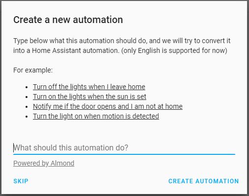
1. Go to Configuration -> Automations, and click the plus icon in the lower right corner. You can skip the first popup window.
2. Give it a name and a description if you want. I recommend giving you descriptive names. Thanks to this, you will know what a specific automation is for without looking inside.
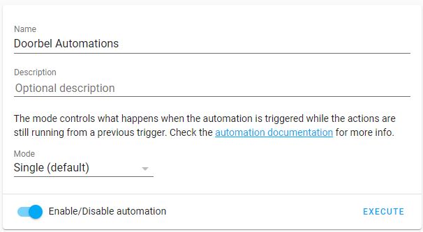
3. Let’s determine what starts the processing of an automation. In our case, it’ll be pressing the button on the doorbell.
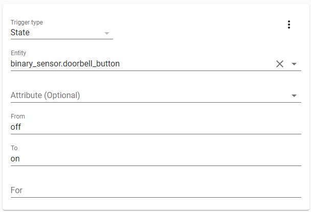
4. If you would like the doorbell to be active only at certain hours of the day, you can do it right here. But for now, just skip it.

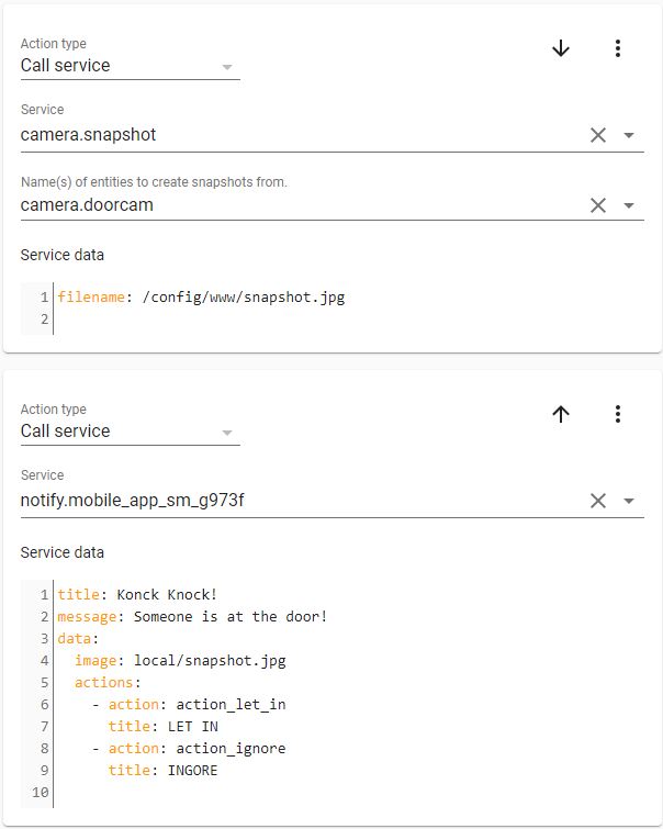
5. Now, we’ll determine what this automation is really supposed to do. As you can see, we have to do two Actions. The order isn’t accidental.
In the first action, we must take a “snapshot” of what the camera is currently seeing, and save it.
In the second action, we’ll send a notification to a specific phone. We’ll add to it our freshly saved “snapshot” and two buttons: LET IN and IGNORE. I don’t need to describe what they will be used for, right? 🙂
Save it!
Now you can ask the question: Why did we save the snapshot in “/ config / www /” and read it from “/ local /“? And the answer is: I don’t know 🙂 If we’re referring to a file in the www folder, type local.
If you know why it works this way, please let me know in the comment.
6. I said in the previous step that we need to save the “snapshot”. There is one more thing we need to do to access this particular directory. In the configuration.yaml file, you need to add an authorization to write files in it.
homeassistant:
latitude: xxx
longitude: xxx
elevation: xxx
unit_system: xxx
time_zone: xxx
name: xxx
whitelist_external_dirs:
– /config/www
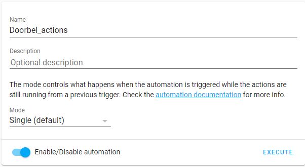
7. Now we need to create a second Automation that takes communication the other way. In other words, it will handle our buttons from the notification.
Same as before – add a new automation. Give it some name and an optional description.
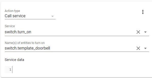
9. The Action will be to turn on the relay in our doorbell.
That’s it! Notification should work beautifully 🙂

Actionable notifications with camera screen on iOS
In the case of iOS, it is a bit easier, and it works better. Instead of a photo, we can receive a live stream in the notification!
However, the procedure for adding Automation is similar. Everything is the same up to step 4. So let’s start with step no. 5.
5. In this step, we’ll set the category of the notification as a camera. It’ll be a live stream.
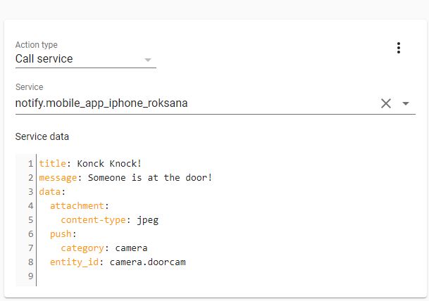
6. We also want to be able to open the gate. We need to add two buttons to the notification to be able to give feedback. To do this, go to the configuration.yaml file and write a few lines of code.
Parameter identifier (the first one) must be the same as the notification category. Additionally, it must only consist of lowercase letters.
Next, let’s write possible actions (i.e. buttons). In this way, we inform the Home Assistant that certain actions may occur with a given notification category. This time parameter identifier refers to the specific button we clicked on our smartphone.
ios:
push:
categories:
– name: Doorbell Alert iOS
identifier: ‘camera’
actions:
– identifier: ‘LET_IN’
title: ‘LET IN’
– identifier: ‘IGNORE’
title: ‘IGNORE’
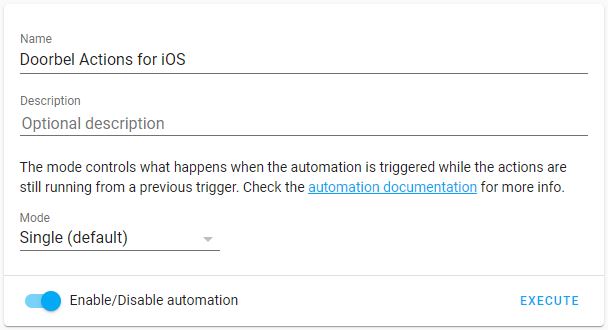
7. Let’s add a new automation. It will be responsible for handling our response (e.g. let a guest in).
You can give any name you like.
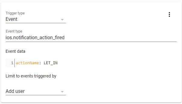
8. The trigger of this automation will be an event received from our iPhone. The most important parameter here is actionName. The name must be identical to the one we entered in configuration.yaml.
In this case, we only need one automation. The second button was IGNORE so that we will do the same 🙂
9. The Action will be to turn on the relay in our doorbell.
That’s it! Let’s check if it works.

Assembly of smart doorbell’s housing
Ok, all components are ready. PCB is soldered, ESP32 is programmed and the case is printed. Let’s put all of them together, and check if it works.
If you want to fix the PCB with classic screws, you can thread the holes first. But it isn’t obligatory. Instead, you can use 3 mm wood screws.
Now place the front panel in the housing. Regardless of whether it is plexiglass or 3D printing, the assembly looks the same. Before you do that, you can put a little silicone glue to make it more trustworthy.

Tighten the four screws to keep the PCB from moving.

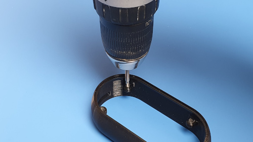
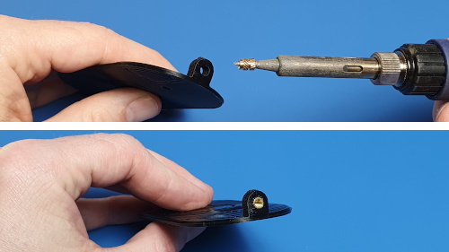
This is another optional step. Personally, I am a fan of Inserted Nuts. I discovered them recently, but I’m planning to use them in every project 🙂 They are easy to install (with a soldering iron), very durable, and look good.
I bought them on Aliexpress.
If you used the inserted nut, you’d need an M3 screw for closing a case. Alternatively, you can also use a wood screw.
The finished Doorbell looks like this. Of course, we’re going to screw it to the wall right away, so we’ll have to take it apart. But it’s only one screw.


Installing Smart Doorbell in the final place
Last stage! The one that gives the most satisfaction. We’ll install our ready, tested, and nice-looking doorbell. And we’ll see you in all its glory 🙂
Because this stage very much depends on the specific place where the doorbell will be mounted. But I will describe what it looked like for me. Maybe it will be an inspiration for you.
When I was installing the gate, I made sure that the wires for the power supply and the solenoid lock were led out in the right place.

I used sheet-metal-screws (if you know a better name for it, please write in the comment) to attach the doorbell and some protection against rain.
Speaking of which, I made a simple shelter to keep it from raining directly on my doorbell. I didn’t describe it separately because there is really nothing to describe. A piece of aluminum sheet bent to pretends to be a roof.
Yes, I know its metal, and it affects the WiFi range. But on the other hand, I attached the whole thing to a big metal pole 🙂 Fortunately, the router isn’t very far away, and the range is sufficient. But if it wasn’t, I could use an external antenna. I wrote more about it in the chapter “Assembly of PCB”.

I drilled a hole in the sheet for wires.

In the back of the case, I also broke a hole for wires. In case of problems, you can use cutters.

I screwed on both the cover and the back of the case in one go.
As it turned out, my screws don’t want to go through thick metal so easily. I had to use a small drill first. It worked without a problem after that.

I connected all the necessary wires. Power supply – 12 VDC and Solenoid Lock – 230 VAC.
Please make no mistake here, because it will be the last moments for a Smart Doorbell 🙂

The last step was to tighten the screw from underneath. It’ll keep the whole case together.

Ok, Smart Doorbell is ready to receive (or ignore) our guests! 🙂


Summary
My doorbell has been working for a while now, and there were no problems with it. However, I plan to make a better cover against rain and maybe bring out an external antenna, just in case. But I am happy with it so far.
Thank you for sticking to the end. If you have any questions or suggestions, write them in the comment section or by e-mail.
Related Articles

SS4H-ZRG Zigbee Rain Gauge – DIY project based Zigbee Door Sensor
In this article, I’m going to show you how to…

SS4H-SSR Smart Extension Board – DIY project based on ESP8266
With these kinds of projects, they are often created when…

SS4H-SHH Smart Home Hub based on ESP32 POE
Personally, I’m a fan of centralized “smart” systems. Thanks to…