
I have a few ideas for simple, smart devices in my smart home that need both Bluetooth Low Energy and WiFi for a long time. I immediately thought about the ESP32 module. Just which board to choose? NodeMCU ESP32 development board (or DEV-ESP32) was my first choice. Unfortunately, this board has several disadvantages which I will talk about later.
Nevertheless, I decided to design an alternative version myself. A version that fully meets my requirements. And that’s how the SS4H-ESP32 Evaluation Board was created.
Introduction
I plan to make a whole series of guides describing real examples of the use of SS4H-ESP32. I’ve used it on two projects now, but I plan to at least two more. Details soon, stay tuned 🙂
Because this is an introduction to the series, the description will be very general. I will focus only on Hardware. I will tell you what possibilities it has and what advantages and disadvantages. Of course, I will also give you all the source files so that you can do this project yourself.
Things that didn’t fully satisfy me in DEV-ESP32 board
Before we start, I will tell you why I didn’t use the popular, ready to use evaluation board. Caution! I’ll be a little whining in this chapter 🙂
- It must be powered from the MICRO USB port (5V). I have 12V in my Smart Home installation. So I would have to use an external voltage regulator.
- The same applies to GPIOs. I would like to be able to connect it directly to 12V and check the status.
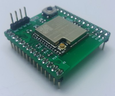
- My first project with ESP32 (spoiler alert ) concerned a mailbox that is far from the WiFi router, so I wanted to be able to connect an external antenna. You can solder to my evaluation board ESP32 WROOM module with an internal or external antenna.
- I also wanted it to be small and visually accepted by my fiancee. Once I try to stick a small PCB (witch no case) to the wall, she said to me: “Are you f**king kidding me?” Since then, my projects are somehow “prettier” 🙂
Don’t get me wrong, I realize that all these problems can be solved in one way or another. Nevertheless, this involves tangled cables which I hate very much 🙂
Main features of SS4H-ESP32 Evaluation Board
- Four isolated binary outputs
- Four isolated binary inputs
- Two analog inputs
- Two general inputs/outputs
- SPI
- I2C
- UART
- Supply voltage between 3,3V and 12V
- The voltage on general pins (Input and Output) up to the voltage level of power supply (max. 12V)
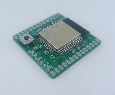
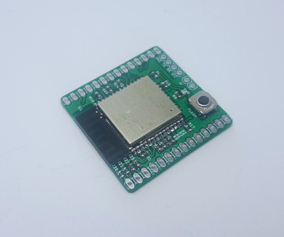
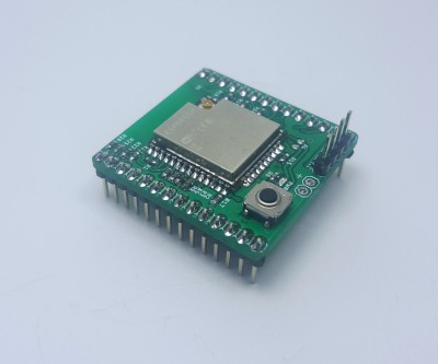
- You can mount the ESP32 module with an external antenna or with an antenna on a PCB
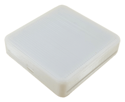
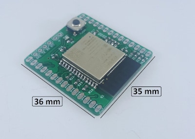
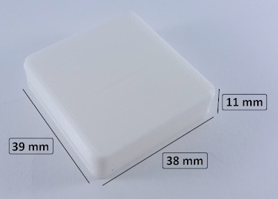
Dimensions
“We live in times where capabilities are increasing, and dimensions do the opposite.” – me 🙂 That is why in each of my projects, I try to fit as many features as possible in the smallest possible case. What I have achieved in this matter you can see in the pictures below.
How do I get this Evaluation Board for ESP32?
Just like in the previous article about Smart Garage Door Opener and each subsequent one, you have two options. You can buy the whole device or selected components from me, or you can use the source files and make the project yourself. Both options are good. Choose which one suits you better 🙂
Hardware
If you want to receive a schematic, PCB layout, and 3D model of the case, just enter the email below – I will send a link to you straight away. If you entered your email on another project, you could use the same link that I sent you then.
Schematic
I designed the board in such a way that it could be powered in a wide voltage range (3.3V – 12V), which has disadvantages. The values of some resistors depend on this voltage level. So, unfortunately, I couldn’t clearly define the specific resistance in the schematic. Pay attention to these three things:
Voltage divider
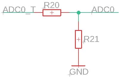
The maximum voltage that you can connect to the ESP32 chip is 3.3V. If you want to measure higher voltages, you need to reduce it somehow. Fortunately, there is a very simple way – voltage divider 🙂
ADC0_T is the voltage you want to measure, e.g., ~12V. ADC0 goes into ESP32, so the maximum value cannot exceed 3.3V. You have to choose the values of resistors R20 and R21 to achieve this. An online calculator may be useful for this purpose.
For example, if the highest voltage you would like to measure is 12V, you can use these values: R20 = 2kΩ and R21 = 680Ω
Optocoupler – input
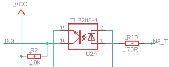
It is an interesting element that I would like to tell you more about 🙂
You are probably wondering why I used optocouplers, GND is common after all, so it isn’t fully separated. I did it because it protects the input chip quite well against voltage stroke. There is never too much protection – believe me .. I already burned a few chips in my life 🙂 The second reason I use the is that there are four transistors in a nice small package. That is saving PCB space.
In this example, the resistor R10 is very important. It limits the current on the diode. It is good if the diode gets at least 10 mA in this configuration. Therefore, if you plan to give 5 – 12V to the binary input, then the resistance 470Ω will be OK. If you want to give 3.3V, then it is good to reduce the resistor value to approx 330Ω.
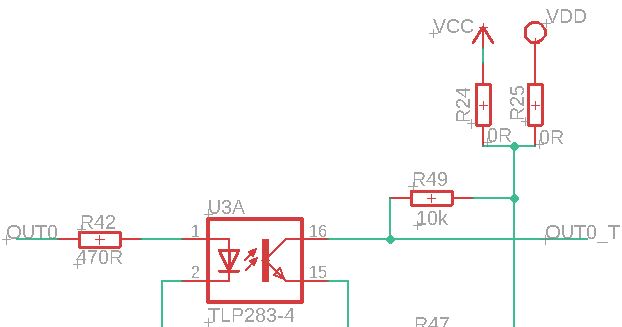
Optocoupler – output
Here, the case is simple. Solder resistor R24 or R25 – never both! Depending on whether you want the GPIO output to be 3.3V (the same voltage as on ESP32), or supply voltage (e.g. 12V)
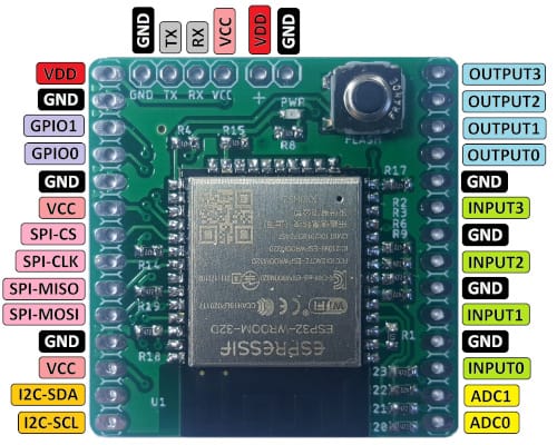
SS4H-ESP32 Pinout Reference
PCB
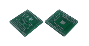
The downloaded files are GERBER, every manufacturer that makes printed circuits boards accepts these files. If you want to preview it, you can use the free GERBV tool. There are also numbers on online viewers. Not all of them work perfectly, but I’m sure you’ll find something useful 🙂
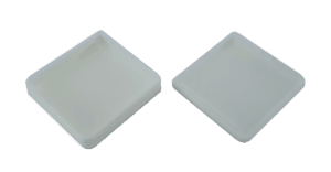
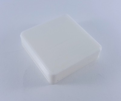
3D printed case
The 3D model of the case is an STL file. If you are printing yourself, you know what to do with this. If you plan to order, just send it to the manufacturer.
I designed this case in such a way that you can solder the wires to the pins you are interested in, and after closing it, there is no risk of short circuit.
Assembly PCB and Case – tips and tricks
- Component assembly is pretty standard. I’m sure you can handle it. Just remember to start with small components (resistors and capacitors). It is easier to operate the soldering tip.
- The ESP32 WROVER module has a heat sink underneath. It is essential for heat removal from the ESP chip. The easiest way to solder this is to use hot air. But it’s possible that you don’t have it in your workshop. That’s why, as an alternative, you can use thermal grease (e.g., for CPU / GPU). Put a thin layer and make sure both surfaces have good contact. I don’t recommend installing this module without making sure that the heat sink has how to dissipate heat.
- If you plan to use the SS4H-ESP32 Evaluation Board as a specific purpose device at your smart home (not for learning and testing). Don’t solder “gold pins”. Instead, solder the wires directly to the pads that interest you – pinout reference. The case has a special gap that allows these wires to be led outside. If you plan to use this board for evaluation purposes, solder these pins, it will be easier to test different configurations. And when you will be ready, just desolder it, close the case and place the device in its final destination.
Gallery
Summary
In this guide, you learned about the technical aspects of this Evaluation Board for ESP32. I hope you find this useful. As I mentioned in the introduction, there will be more articles in which I will describe in detail my “smart” projects based on this board.
If you have any problems (e.g., with choosing the right values of resistors) or you think I wrote something in a too complicated way, just write me an email: contact@smartsolutions4home.com.
Related Articles

SS4H-ZRG Zigbee Rain Gauge – DIY project based Zigbee Door Sensor
In this article, I’m going to show you how to…

SS4H-SSR Smart Extension Board – DIY project based on ESP8266
With these kinds of projects, they are often created when…

SS4H-SHH Smart Home Hub based on ESP32 POE
Personally, I’m a fan of centralized “smart” systems. Thanks to…