
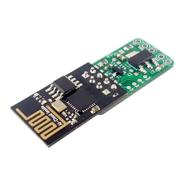
The ESP-01S module needs no introduction. It is probably the smallest and cheapest module with the ESP8266 chip that you can currently buy. For this reason, it is extremely popular in all kinds of projects where WIFI is needed. I wrote more about this and other modules in the guide Programming ESP8288.
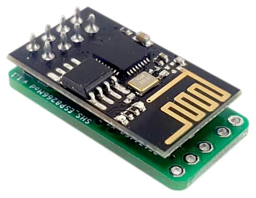
In this short article, I will describe my last project designed to work with ESP8266. It is the smallest and most universal board for the ESP-01S module. I’m writing these words with full awareness 🙂 If something smaller or more universal appears, I will come back and correct this paragraph – I promise.
Introduction
In Smart Homes, very often, we don’t need an advanced microcontroller, multiple GPIO pins, analog inputs, and several communication buses. Usually, the device has only one function. For example, a simple wall button, temperature/humidity sensor, motor controller, or presence sensor.
This module is ideal for such applications. However.. usually, some components are needed between the module and whether this module is to deal with it. Maybe the power supply has a different value, or the sensor gets too high voltage, or we just want to control something that needs more current than the ESP8266 gives. That’s why I designed the SS4H-ESP-01. You can put everything you need between the device and the ESP module on it. And best of all, its dimensions don’t exceed the module itself!
So you don’t have to create a huge spider of tangled cables or mount it on a breadboard 🙂
Main features
The board can be configured in several different ways. Depending on the assembled components, it will perform a different function. Besides, you have a lot of freedom in terms of power supply. I will describe more features in chapter Configurations.HereI only mention these.
- you can use a different voltage to power the device, another one to control the sensor/actuator, and another to power the ESP8266 module,
- you can connect the GPIO directly to the data pin,
- you can solder transistors between them if the voltages are different or if you need more current,
- you can use pull-up from pull-down if required.
I realize that this may be unclear for now, but everything will become more apparent when you look at the schematic.
Hardware
As in all my previous projects, I will provide you with my source files. If you want to receive all of them, just enter the email below – I will send a link to you straight away.
If you entered your email on another project, you could use the same link that I sent you then.
PCB

The size of the PCB is very similar to the size of the ESP-01S module itself, which was one of my main priorities.
You will find GERBER files in the package you received from me. It is the standard format used by PCB industry. It describes how the board looks. Each layer (copper, overlay, solder mask) is a separate gerber file.
If you outsource it to someone, just them send these files, they will know what to do 🙂
However, if you want to do it yourself, I recommend the free tool: GERBV. It allows you to view all layers and also export them to “pdf”, “png” or simply to print it. If you’ve ever made PCBs yourself, I’m sure you know what the next steps are.
Configurations
As I mentioned earlier, the board can be configured in several different ways. To systematize the configurations in some way, I divided the whole process into several functional blocks:
- Power supply
- Communication
- Orientation
- Flashing
Power supply
The board has space for two linear voltage regulators (LDO) in a SOT-223 package. So you can use three different voltages at one time:
- primary supply voltage – V0,
- actuator voltage – V1,
- ESP8266 module supply voltage (3.3V) – V2.

Please note that V0 ≥ V1 ≥ V2. The output from LDO1 is the input to LDO2. It follows that the voltage you can use is between 12 – 3.3 V. Because V2 is the ESP module supply and it must be 3.3V.
This solution may seem unnecessarily complicated, but it can often be useful, and I’ll prove it to you right away 🙂
Thanks to this you can use 12 V to power the entire device, connect to a 5V relay, and power up the ESP8266 module accordingly with 3.3 V. But if you don’t need such a variety of voltages, you can skip both LDOs and power the device with 3.3 V external power supply.
How to set the correct voltage?

V0 is the voltage connected directly to the power connector. It is connected to LDO1.

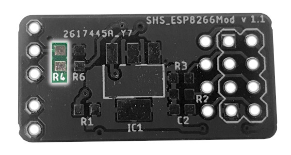
V1 is the voltage at the LDO1 output (on the PCB I named it IC2). If you want to skip LDO, solder the resistor R5 – 0Ω (jumper) instead.

V2 is the voltage at the output of LDO2 (on the PCB I named it IC1). If you want to skip this LDO, solder the resistor R1 – 0Ω instead. I have already talked about it, but I will repeat it because it is crucial. This voltage directly powers the ESP8266 chip, so it must be 3.3 V. Otherwise, you will damage it.
Communication
Your device can act as an input or output. Depending on what you connect to the DATA pin. It can be a sensor, switch, relay, or anything else. On this board, you have many options for connecting them with ESP8266. You can do it:
- directly (input/output),
- through the transistor NPN (input/output),
- through a voltage divider (input),
- with pull-up (input/output),
- with pull-down (input/output).
As you can see, you have a lot of freedom when it comes to the way of communication. I tried to fit in as much as I could 🙂
Let’s follow each of these options now.
Directly (input/output)
If you want to connect the device directly, solder R4, R7, and R11. The value of resistors is 0Ω. On the other hand, if you’re going to limit the current (for some reason), you can give a little bigger resistor instead.

Through the transistor NPN (input)
If your device works as an input, but the sensor on the output has 5 V or 12 V. Then, you have to reduce the voltage to 3.3 V. Otherwise you will damage ESP8266. One solution is to use an NPN transistor.
In that case, the configuration will look like this:
- R4, R7 – 0 Ω
- R12 – 1 kΩ
- T2 – transistor NPN
- JP1 – 4,7 – 10 kΩ
Through the transistor NPN (output)
If your device works as an output, and the actuator, you want to control needs 5 or 12 volts. Or you need 3.3 V, but more current than the ESP chip allows. Then using a transistor does the trick. Here’s what you need to mount on the PCB:
- R4, R11 – 0 Ω
- R8 – 1 kΩ
- T2 – transistor NPN
- JP1 – 4,7 – 10 kΩ
Through a voltage divider (input)
In case your device works as an input, you can use a voltage divider instead of a transistor. It is the easiest way to lower the voltage. All you need is two resistors. The values depend on the input/output voltage and current. You’ll find a great online calculator on allaboutcircuits.com.
For example, when the sensor uses 5V for communication.
- R4 – 1,2 kΩ
- R6 – 2 kΩ
In that case, the output voltage will be 3.1 V. Which is a safe value for the ESP8266 chip

With pull-up (input/output)
Some sensors require that the data line be pulled up to VCC. A good example is the DHT22 temperature and humidity sensor. For it to work, it needs a resistor between the data line and the VCC.
What to solder:
- R4, R7, R11 – 0 Ω
- JP1 – the resistance depends on the particular case, typically 4.7 – 10 kΩ

With pull-down (input/output)
I can’t come up with a specific example for pull-down right now. If you have any idea, let me know in the comment 🙂 However, if you need to pull the data line to GND, then you have that option.
What to solder:
- R4, R7, R11 – 0 Ω
- R6 – the resistance depends on the particular case, typically 4.7 – 10 kΩ

Orientation
You can mount the ESP8266 module in two ways, depending on how you need it to be small. I described these two ways below.
Method 1
It is mounting directly over the board. In this case, the dimensions are 15/28/9 mm. It may cause a slight reduction in range because there is copper under the antenna. However, at my home, it works without a problem for several meters and two walls in between. You need to test how it works for you.
Method 2
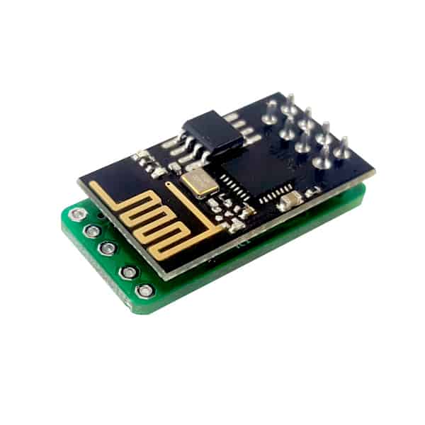
It is mounted “next to” the board. If you need it to be an extra flat you can install it this way. In this case, the dimensions are 15/44/5 mm. An additional advantage is the better range, because the antenna is further away from metal components.
Ps. you can remove the plastic insulators from the pins.
Flashing
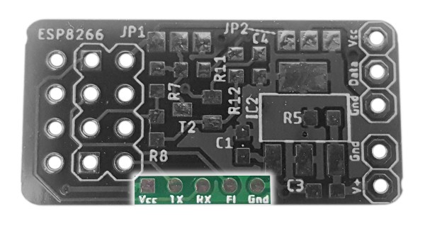
I wanted the module to be as small as possible, which is why there are no classic programming pins. There are only small pads. You can use test pins (with a spring), or solder the cables directly to the USB-UART adapter. Choose what is more convenient for you.
It is also possible to program with ordinary gold-pins, but you need to press them firmly against the pads. I did it more than once – it can be done 🙂
Pay attention to one extra pad – FL. It determines whether the module will enter programming or normal operation mode. If you want to flash the chip, it must be shorted to ground when connecting the power supply.
Summary
In this article, you learned about the technical aspects of the smallest and the most universal board for the ESP-01S module. I hope I made it clear and find it useful. There will be more articles in which I will describe in detail my “smart” projects based on this board. Stay tuned!
Write in the comment on how you would use such a module. Maybe it will be an inspiration for others 🙂
If you have any problems (e.g., with choosing the right values of resistors) or you think I wrote something in a too complicated way, just write me an email: contact@smartsolutions4home.com.
Related Articles

SS4H-ZRG Zigbee Rain Gauge – DIY project based Zigbee Door Sensor
In this article, I’m going to show you how to…

SS4H-SSR Smart Extension Board – DIY project based on ESP8266
With these kinds of projects, they are often created when…

SS4H-SHH Smart Home Hub based on ESP32 POE
Personally, I’m a fan of centralized “smart” systems. Thanks to…