
In this article, I’ll walk you through every step of how I built my very own Shadow Display—and show you how to create one yourself. I’ve chosen to turn mine into a sleek, minimalist clock, but the beauty of this open-source project lies in its flexibility: you can decide how many digits to display, separator style and adapt it in the way that suits your taste.
All the design files, firmware and assembly guides are freely available, so feel free to download, tinker and customize to your heart’s content.
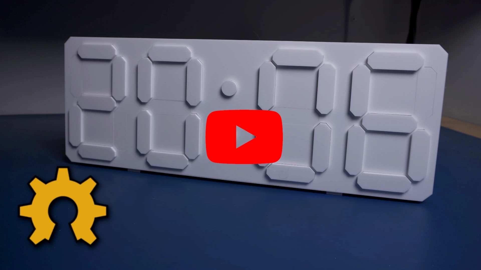
Video version
If you prefer watching over reading, I’ve got you covered. Check out the video where I walk through the whole process.
Source files
The project is totally open-source, which means you can grab it and tweak it however you please. Since this project is basically a spin-off of the “7-Flip Display” project, you can grab most of the files straight from there. You can snag my design, the PCB layout, the 3D model, the bill of materials, and firmware – and make it exactly as is. Or, you can use it as a jumping-off point, make changes, and whip up something totally fresh.
Where can I buy it?
If you don’t have the time—or just can’t be bothered to build that display yourself—swing by my store. You might find something there that catches your eye.
JLCPCB
The sponsor of this project is JLCPCB. They made that beautiful board for this project. For a few bucks, and in a matter of days, you can have a professional PCB on your deck, ready to solder 🙂 Now, for new users, they provide up to $70 sign-up coupons.
And if you don’t feel up to it, they can solder all SMD components for you as well.
Electronic

At the core of this project sits an ESP32, responsible for managing the display segments and handling Wi-Fi communication with a web application or Home Assistant.
To switch the electromagnetic coils, the design uses H-bridges. They allow current to flow in either direction, effectively reversing the magnetic polarity when needed.
A single H-bridge requires two GPIO pins for control, which would result in 14 GPIOs per module—an unrealistic number. Building a four-module clock would demand 56 GPIOs, making the design unnecessarily complex and impractical.
To solve this, the system uses shift registers, reducing the required GPIO count to just three, regardless of how many modules are connected.
The device also includes a Real-Time Clock with a battery backup. Once the time is set, the clock can operate fully offline. Even in the event of a power outage, it continues keeping time and automatically resynchronizes when power is restored.
A bit of theory behind the components I used:
Understanding Magnetic Actuation for Segments
At the heart of this project is the magnetic actuation that moves each segment. How does a coil of wire make a plastic segment move, and why do we need the current to go both ways? Let’s break down the principles:
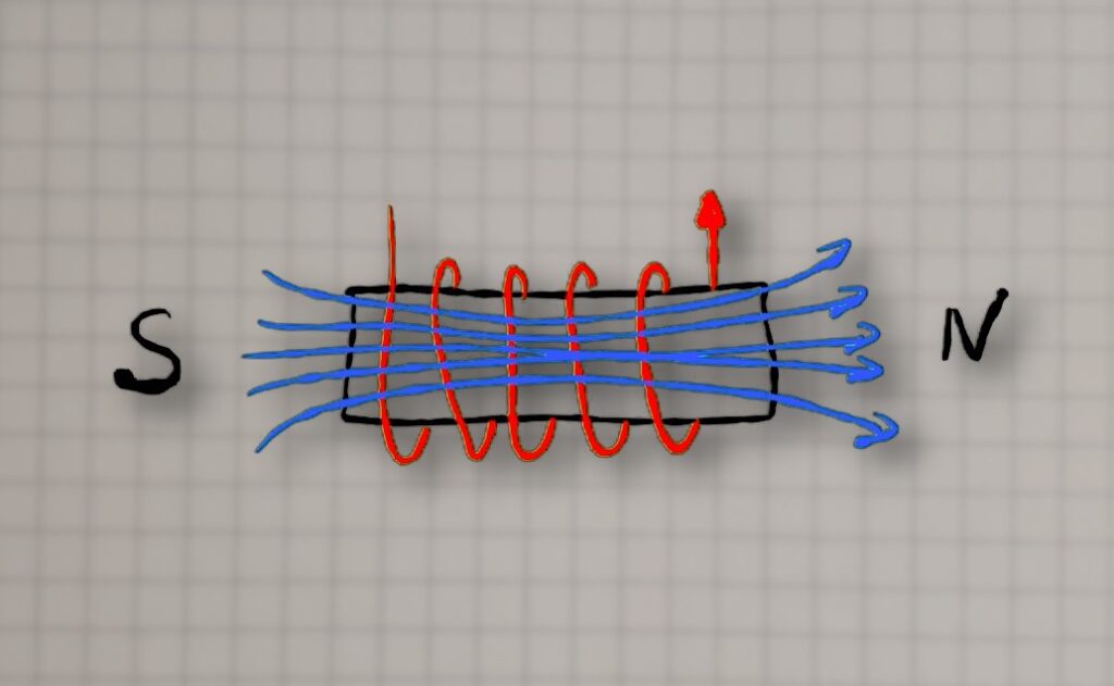
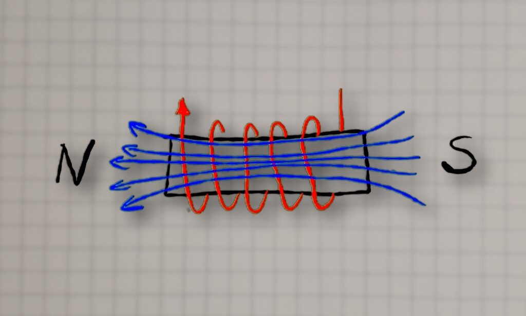
Electromagnets 101: When current flows through a wire coil, it generates a magnetic field. One end of the coil becomes a north pole and the other a south pole (depending on current direction). If you place a permanent magnet nearby, that magnet will experience a force: opposite poles attract and like poles repel. In our display, each segment has a small neodymium magnet attached. By energizing a coil behind the segment, we can either attract or repel the magnet, causing the segment to flip inward or outward.
Magnetic Force Considerations: The strength of the magnetic push/pull depends on a few factors: the coil’s current, the number of turns in the coil, and whether there’s a core material to concentrate the field. Higher current and more turns make a stronger electromagnet. Traditional electromagnets use an iron core to greatly boost the field, but our PCB coils are air-core (just copper and air). To compensate, I designed the PCB coils with multiple turns and layers to generate as strong a field as possible within the space constraints. Through some experimentation, I found that about 30 turns spread over 4 PCB layers worked well for flipping the small magnet/segment reliably,
In summary, by leveraging magnetic attraction and repulsion, we can get a crisp mechanical motion for each segment. Next, let’s see how we drive these coils electrically – this is where the H-bridge drivers come in.
H-Bridge Drivers
To flip a segment, we need to send current through its coil in either direction as needed. Manually swapping wires to reverse a coil would be impractical, so we use an electronic solution: an H-bridge circuit. An H-bridge is a configuration of four switches (often transistors or MOSFETs) arranged like the letter “H”, with the load (our coil) in the center. By closing two opposite switches at a time, current can flow through the coil in one direction; closing the other two switches sends current the opposite way. This is a common method to control DC motors as well – it allows you to drive motors forward or backward, or in our case, magnetize the coil as north-up or south-up.

Shift Registers

Each H-bridge needs two control lines. So if you’re working with, say, six modules—that’s 42 segments, meaning you’d need 84 GPIOs. You’d also have to route all those signals between modules, which would be an absolute nightmare. Not to mention, the display wouldn’t be expandable.
That’s where shift registers (e.g. 74HC595) come in.
Here’s how it works in our context: The microcontroller sends a stream of bits (corresponding to the desired on/off states of each segment coil) into the shift registers serially. Once all bits are shifted in, a latch pin is toggled to transfer those bits to the output pins of the 74HC595s, which are connected to the H-bridge driver inputs. By daisy-chaining, for example, two 74HC595s, we get 16 outputs.
Each segment needs two outputs to drive its H-bridge—so that’d be 14 outputs per module. To keep the wiring simple, I just stick two 8-bit shift registers in each module. Yeah, it “wastes” a couple of pins, but those chips are dirt cheap, so who cares? Plus I use one of those outputs to feed a feedback signal back to the microcontroller. So basically, there’s really only one output that isn’t used.
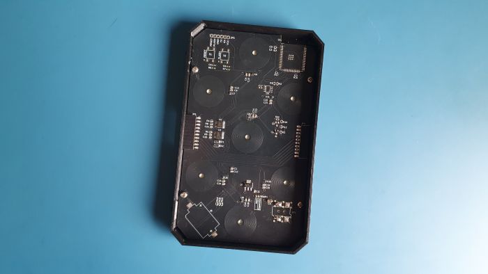
PCB


A few quick notes about the PCB:
I usually try to keep all the SMD components on the same side of the board. But in the case of the main module, for obvious reasons, I had to place the LED on the opposite side from the rest of the components. So, if you want to use that LED, you’ll have to solder it by hand. Luckily, it’s a fairly large one, so even a basic soldering iron tip should do the trick.
The only component that might give you a bit of trouble is the coil driver (DRV8231) in a WSON8 package. Technically, you can solder it with a regular iron, but I’d really recommend using solder paste and either a reflow oven, a hot plate, or at least a hot air station. It’ll make your life way easier.
Everything else is pretty standard and shouldn’t give you any problems.
The PCBs for the main module and all the expansion modules are literally identical—that really streamlines production. They only differ in which components you actually solder onto them.

Main Board
On the main board, aside from the microcontroller, there’s also an RTC chip and a coin battery. So if you want to use it as a standalone clock, completely offline—you totally can.
As for the power connector—on my setup, it’s on the main module, but you can place it on any module. That means your display can be powered from the right side, the left, or even from the middle—whatever works best for your layout.
Extension Board
The PCB for the extension modules is identical—the only difference is what gets soldered onto it.
It’s actually way simpler. It really just uses shift registers, H-bridges, and an LDO to power the electronics.
Mechanics
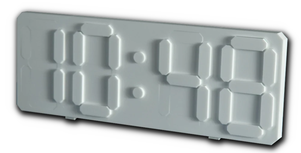
In the original design, active segments appeared white, while inactive ones blended into the black enclosure. In this updated version, everything is white. That immediately raises an important question: how do you distinguish between active and inactive segments? The answer lies not in color, but in light—specifically, shadow.
Inactive segments sit perfectly flush with the front panel. When activated, a segment rises a few millimeters, creating a subtle shadow that reveals its shape. It’s a minimal, elegant effect driven entirely by depth and lighting.


Shadow
Of course, this approach comes with trade-offs. The display won’t always be equally readable in every environment. Depending on the viewing angle or lighting conditions, contrast may vary. But placed thoughtfully—near a window, beneath a lamp, or in a naturally directional light source—the result is striking and visually unique.
To achieve good readability, a few design elements are crucial. The front surface must remain smooth, uniform, and consistently white. Off segments should blend in almost completely, remaining invisible until activated.


Unfortunately, traditional FDM 3D printing isn’t ideal here. For the segments to move freely, they must be noticeably smaller than their openings, resulting in a visible gap. Layer lines and perimeter patterns further disrupt the clean aesthetic. MSLA resin printing offers much greater precision, but build volume is limited. This works well for separate, modular digits—but in this project, the goal was a seamless, continuous front panel with no visible breaks.
And that’s where the CO₂ laser comes in.
It’s basically made for cutting all kinds of plastics like acrylic. Since the cutting surface is way smoother than with 3D printing, I was able to really tighten the gap between the segment and the front panel. That means when the segment is off and you look at it from the right angle, it’s barely visible—which was exactly what I was going for.

SOFTWARE/FIRMWARE

To program the display, you’ll need a simple USB–UART adapter (any cheap one will do). In the original project article (LINK) you’ll find a detailed, step-by-step guide to the programming process, along with all the necessary files. Once the firmware is uploaded, the device becomes essentially plug-and-play.
If you haven’t seen the original project yet, it’s worth taking a look (LINK). It walks through all the configuration steps in detail, so there’s no need to repeat them here.
Conclusion
Thanks for sticking with me till the end of this article. Hope you enjoyed this alternative version of my other electromechanical display!
I hope this comprehensive walkthrough becomes a go-to resource for anyone looking to recreate or expand on this project. Whether you’re showcasing follower counts, crafting a unique clock, or simply diving into electromechanical displays, there’s plenty of joy and discovery in building something that literally moves, clicks, and exists in the real world.
Feel free to use the provided files and code to make your own, and let me know if you do – I’d love to see more of these displays out there. Happy building, and happy flipping!
Related Articles

SS4H-ZRG Zigbee Rain Gauge – DIY project based Zigbee Door Sensor
In this article, I’m going to show you how to…

SS4H-SSR Smart Extension Board – DIY project based on ESP8266
With these kinds of projects, they are often created when…

SS4H-SHH Smart Home Hub based on ESP32 POE
Personally, I’m a fan of centralized “smart” systems. Thanks to…