
Ever wanted a display that flips real, physical segments like the electromechanical signs of old, but with modern Wi-Fi control? In this project, I build a custom 7-segment electromechanical display that combines retro flip technology with IoT convenience. Each segment is moved by an electromagnetic coil printed on the PCB itself – no bulky solenoids needed – and an ESP32 microcontroller updates the display via Wi-Fi. The result is a satisfying clack of moving parts whenever the digits change, and a device that holds its state without constant power. In this in-depth guide, I’ll explain how it works and how you can build one, covering everything from magnetic actuation principles and H-bridge drivers to using shift registers for many segments. Let’s dive into this blend of old-school mechanics and new-school electronics!
Video version
If you prefer watching over reading, I’ve got you covered. Check out the video where I walk through the whole process.
Source files
The project is totally open-source, which means you can grab it and tweak it however you please. You can snag my design, the PCB layout, the 3D model, the bill of materials, and firmware – and make it exactly as is. Or, you can use it as a jumping-off point, make changes, and whip up something totally fresh.
Where can I buy it?
If you don’t have the time—or just can’t be bothered to build that display yourself—swing by my store. You might find something there that catches your eye.
JLCPCB
The sponsor of this project is JLCPCB. They made that beautiful board for this project. For a few bucks, and in a matter of days, you can have a professional PCB on your deck, ready to solder 🙂 Now, for new users, they provide up to $80 sign-up coupons.
And if you don’t feel up to it, they can solder all SMD components for you as well.
Project Overview
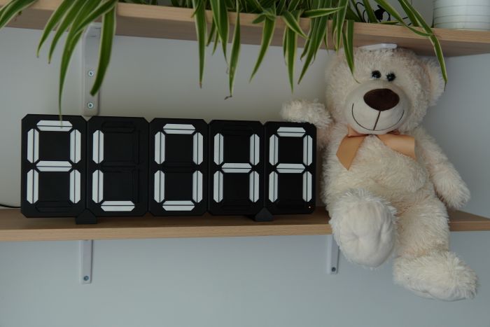
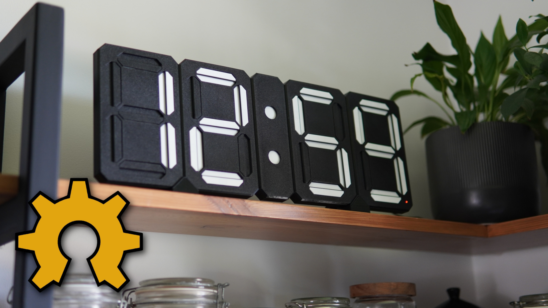
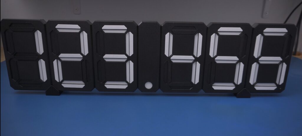
What Does the Display Do? Essentially, it’s a 7-segment display (think of the digits on a digital clock) where each of the seven segments is a physical piece that can flip between two states (visible or hidden, or even two different colors) through magnetic actuation. An ESP32 microcontroller connects to Wi-Fi and updates the numbers displayed – for example, showing a live YouTube subscriber count or the current time – by sending commands to the segments. Unlike an LED display, this electromechanical version makes a satisfying click and clack when segments flip, and once a segment is flipped to a position, it stays in that position without needing power until it’s flipped again.
General concept

In this post, let’s break down a few key terms so we’re all on the same page: the smallest movable part is called a SEGMENT, and you can turn it on or off independently of the others. Seven of these come together to form a MODULE, which can display a single digit or symbol. The first module is the MAIN one—it houses the microcontroller and acts as the brain of the whole operation—while the rest are EXTENSION modules. In theory, you could have as many as you want, but factors like voltage drop and communication speed impose a practical limit. This little module here is the SEPARATOR; it could be a colon, a dot, or a dash. All of this combined makes up the DISPLAY, and even though I talk about it in the singular, it can handle several completely independent tasks at the same time. That’s why I’ve introduced one more term: GROUP, which I’ll explain when I cover modes. As mentioned, the project is fully open-source—you can download all the files you need to build it yourself for free (check out my website for more info). But if you’d rather save some time and hassle, feel free to swing by my store.
Understanding Magnetic Actuation for Segments
At the heart of this project is the magnetic actuation that moves each segment. How does a coil of wire make a plastic segment move, and why do we need the current to go both ways? Let’s break down the principles:
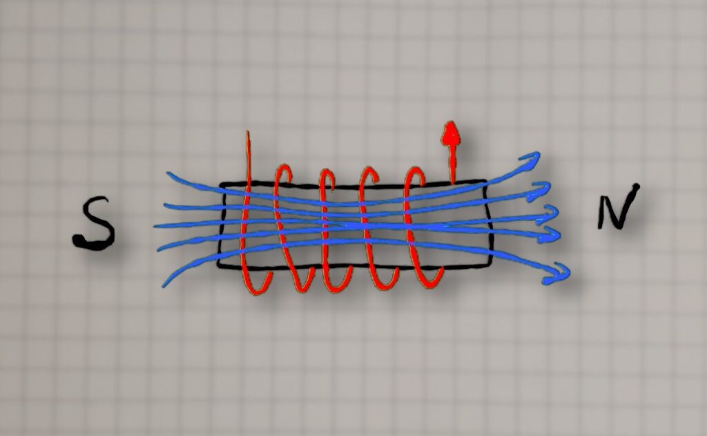
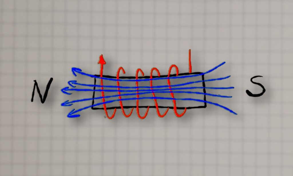
Electromagnets 101: When current flows through a wire coil, it generates a magnetic field. One end of the coil becomes a north pole and the other a south pole (depending on current direction). If you place a permanent magnet nearby, that magnet will experience a force: opposite poles attract and like poles repel. In our display, each segment has a small neodymium magnet attached. By energizing a coil behind the segment, we can either attract or repel the magnet, causing the segment to flip inward or outward.
Magnetic Force Considerations: The strength of the magnetic push/pull depends on a few factors: the coil’s current, the number of turns in the coil, and whether there’s a core material to concentrate the field. Higher current and more turns make a stronger electromagnet. Traditional electromagnets use an iron core to greatly boost the field, but our PCB coils are air-core (just copper and air). To compensate, I designed the PCB coils with multiple turns and layers to generate as strong a field as possible within the space constraints. Through some experimentation, I found that about 30 turns spread over 4 PCB layers worked well for flipping the small magnet/segment reliably,
In summary, by leveraging magnetic attraction and repulsion, we can get a crisp mechanical motion for each segment. Next, let’s see how we drive these coils electrically – this is where the H-bridge drivers come in.
H-Bridge Drivers
To flip a segment, we need to send current through its coil in either direction as needed. Manually swapping wires to reverse a coil would be impractical, so we use an electronic solution: an H-bridge circuit. An H-bridge is a configuration of four switches (often transistors or MOSFETs) arranged like the letter “H”, with the load (our coil) in the center. By closing two opposite switches at a time, current can flow through the coil in one direction; closing the other two switches sends current the opposite way. This is a common method to control DC motors as well – it allows you to drive motors forward or backward, or in our case, magnetize the coil as north-up or south-up.

Shift Registers

Each H-bridge needs two control lines. So if you’re working with, say, six modules—that’s 42 segments, meaning you’d need 84 GPIOs. You’d also have to route all those signals between modules, which would be an absolute nightmare. Not to mention, the display wouldn’t be expandable.
That’s where shift registers (e.g. 74HC595) come in.
Here’s how it works in our context: The microcontroller sends a stream of bits (corresponding to the desired on/off states of each segment coil) into the shift registers serially. Once all bits are shifted in, a latch pin is toggled to transfer those bits to the output pins of the 74HC595s, which are connected to the H-bridge driver inputs. By daisy-chaining, for example, two 74HC595s, we get 16 outputs.
Each segment needs two outputs to drive its H-bridge—so that’d be 14 outputs per module. To keep the wiring simple, I just stick two 8-bit shift registers in each module. Yeah, it “wastes” a couple of pins, but those chips are dirt cheap, so who cares? Plus I use one of those outputs to feed a feedback signal back to the microcontroller. So basically, there’s really only one output that isn’t used.
Microcontroller
When it came to picking the microcontroller, I didn’t have to think too hard—I went with the ESP32, because honestly, it’s just great. It has built-in Wi-Fi and BLE, a solid amount of RAM and flash storage, it’s fast, and you can program it in a bunch of different environments.

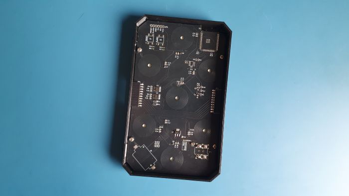
PCB
With the core concepts sorted out – coils, magnets, H-bridges, and shift registers – I proceeded to design the PCB that ties it all together. The PCB serves multiple roles: it holds the spiral coil for each segment, the driver circuitry, and connectors for power and control signals.
PCB Coils Layout: Laying out PCB coils was an interesting challenge. I needed the coils to be as space-efficient and as powerful as possible. Luckily, Fusion 360 has this neat ULP for generating coils, so I didn’t have to draw them by hand. It was just a matter of deciding the number of turns, layers, and trace width. After lots of testing, I settled on 4 layers with 24 loops each—96 turns total—and a 0.3 mm trace width. That setup worked best.
The PCBs for the main module and all the expansion modules are literally identical—that really streamlines production. They only differ in which components you actually solder onto them.

Main Board
On the main board, aside from the microcontroller, there’s also an RTC chip and a coin battery. So if you want to use it as a standalone clock, completely offline—you totally can.
As for the power connector—on my setup, it’s on the main module, but you can place it on any module. That means your display can be powered from the right side, the left, or even from the middle—whatever works best for your layout.
Extension Board
The PCB for the extension modules is identical—the only difference is what gets soldered onto it.
It’s actually way simpler. It really just uses shift registers, H-bridges, and an LDO to power the electronics.
Mechanics
This part of the project is absolutely key to how the display looks and works.
Tolerance is everything here. The flaps have to move smoothly, freely, and with zero sticking. If yours end up feeling too stiff, the easiest fix is to dial down the flow rate in your slicer.
Color Choices & Printing
I chose black for the housing and the “off” segments, and white for the “on” segments—but feel free to pick any color combo that speaks to you. If you have a multi-material printer (MMU, AMS, or any automatic filament-switcher), go ahead and print everything in one go. No such luxury? No problem. I simply printed the black and white parts separately and glued them together with a bit of super-glue. You can also swap filaments manually mid-print if you prefer.

One small detail I care deeply about is a consistent surface finish on all the front-facing panels. To achieve that, I lay those parts flat on the print bed with their visible side down as the very first layer. The result: a uniform, professional-looking texture across the board.
One more tip: print your flaps at a 0.1 mm layer height. You can do the rest at 0.2 mm, but for the flaps stick with 0.1.
Module Connectors & Expansion
The main module only needs an output connector to talk to whatever comes next in the chain. Each extension module, except the last one, carries both input and output connectors. From the outside, they all look essentially identical—that was entirely intentional, for a sleeker, more modular aesthetic.

I also added an optional RGB LED to the main module. You don’t have to include it, but I find it incredibly handy: a quick glance at the color tells me if the device is online, healthy, or actively receiving data from the web app, an API, or even an MQTT broker.
Magnetic Latching with Minimal Power
Here’s a trick that might not be obvious at first glance: on the back cover I screwed in seven tiny bolts.

Copper coils on the PCB aren’t ferromagnetic, so once you cut power, the flaps would just flop open. By embedding small permanent magnets inside each flap and giving them a steel surface to latch onto, the coil only needs about 100 ms of power to flip the flap—and then it can go completely dark, drawing zero current until the next change.
Fool-Proof Alignment

I’ve seen too many frustrating DIY projects ruined by backwards connections. To stop anyone from plugging a module in the wrong way, I added little notches and bumps around the connector. Plug it in backwards and you’d send 9 V into pins only rated for 3.3 V—trust me, that ends in smoke.
Assembly & Connectivity
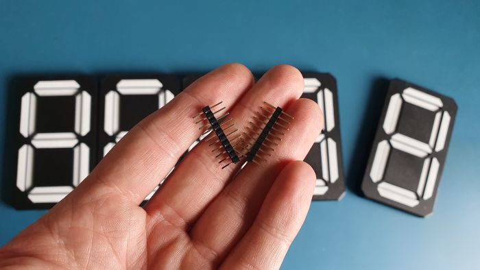
For the electrical link between modules, I stuck with good old male-to-male pin headers—the same trick I used in my Home Assistant hub project, and it worked flawlessly. For the mechanical side, snap-in clips make everything click together in seconds: just press until you hear that satisfying click, and you’re good to go.
Configurability
Right from the start, I knew this had to be a truly modular, all-purpose display. The goal? Let you tailor the setup to exactly what you need—whether that’s a classic clock face or a scrolling custom message.
You can place it on a shelf or mount it on the wall. The power connector isn’t locked into the first module; slide it into whichever segment makes sense for your layout. Want an LED status indicator in the main module? Go for it. Don’t want one? Leave it out.
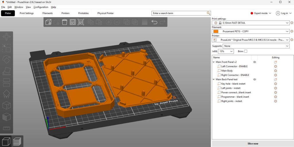
All together, that adds up to virtually endless possible configurations—but managing all those options shouldn’t be a headache. That’s why I’ve wrapped everything into a single, feature-toggled design file. Simply flip the toggles in your slicer to turn features on or off—you’ll find the options right in your PrusaSlicer setup (and any other modern slicer should handle it just as smoothly).
To keep your layout crisp and readable—especially for things like time or dates—I’ve designed a “separator module” that contains no moving parts. Think of it as your visual punctuation: it can be a colon, a dot, a comma, or even just empty space.
Despite its passive role, each separator still carries its own PCB so power and control signals flow through seamlessly to the next module in line. From the microcontroller’s perspective, it’s completely invisible: it doesn’t process any commands or draw current, it simply passes everything along unchanged.

Want to stack rows—say, two lines of text or numbers? Just jumper the last module of the first row to the first module of the second row. The firmware doesn’t care about your physical arrangement; as long as each module’s ten pins are wired correctly, your entire display will spring to life exactly as you’ve laid it out.

Firmware
Until now, nearly every one of my projects has been built on ESPHome—and for good reason. If you want to hook your device straight into Home Assistant, it’s an amazingly simple solution. It even handles shift-registers out of the box, which are central to this build—so yes, you can absolutely stick with ESPHome if that’s what you prefer.
That said, ESPHome’s greatest asset—its ease of use—can also be its biggest limitation. You’re required to use Home Assistant to tweak settings or switch modes, and it doesn’t give you full low-level control of the ESP32 hardware.
To really unleash the ESP32’s power, you need to drop down a layer closer to the metal. That’s why, for this project, I switched to ESP-IDF, Espressif’s official IoT Development Framework. It lets you dive deep into the chip’s capabilities—timers, peripherals, power-management features, and more—without the abstracted constraints of a higher-level tool.
Don’t worry, though: choosing ESP-IDF doesn’t lock you out of Home Assistant. You can still integrate the display seamlessly, and you’ll even gain the ability to drive it simultaneously from Home Assistant and my custom web app—no reflashing required. You just program it once, and after that you can tweak the device any way you like through the GUI. So afrer that you can toss that programmer into a drawer 🙂
Flashing
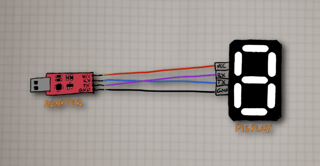
To program the ESP32 chip, you just need any super-cheap USB–UART adapter that supports 3.3 V logic—you can grab one for pennies on Amazon, Aliexpress or eBay. Hook VCC to VCC, GND to GND, RX to TX, and TX to RX.
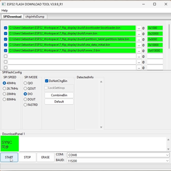
Next, open the “Flash Download Tool”. It’s a handy program that lets you flash several binary files—each to its own address—in one go. To get the ESP32 running properly, you’ll need to flash the bootloader, the partition table, the main firmware, and the web app. It sounds complicated, but just follow the screenshot I showed you. You can find all the files in the “build” folder of the project repo on my GitHub.
WEB Application and Display Features
As I mentioned earlier, once you’ve flashed the display, you won’t have to do it again—unless you decide to modify the firmware yourself. You’ll configure the display, split it into groups, and assign modes all through the web app. Updates work the same way: you can remotely update both the firmware and the application. All you need is a Wi-Fi connection to the internet.

First-Time Setup & Network Configuration
When you power on the display for the very first time, it automatically boots in Access Point mode—creating its own Wi-Fi hotspot so you can get up and running in seconds.
When you connect to that network and go to 192.168.4.1, you’ll see the web app. It’s fully functional—you can already switch modes, split into groups, or manually click segments. But it’s not very convenient, since you have to disconnect from your local Wi-Fi to join the hotspot. OTA updates and the “Custom API” mode won’t work either, because the display has no Internet access.
Think of this Wi-Fi mode as just the initial setup, where you configure the connection to your local network.
Head into the Wi-Fi settings and switch to “Wi-Fi client mode.” Then enter your network’s SSID and password. Hit “SAVE,” and the device will store those settings and reboot—this time without creating a hotspot. From now on, it’ll always start up in client mode.
If you ever change your network info or move the display to a different network, it obviously won’t be able to connect. That’s why I added an ESPHome-style fallback: if the device can’t join Wi-Fi for any reason within 60 seconds of booting, it’ll drop back into AP mode so you can correct the SSID or password.

Remote update
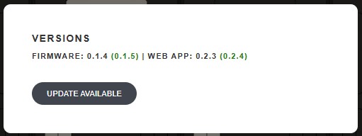
As for remote updates, when a new firmware is available, you’ll see a notification right there. If you want to install it, just click Update and wait a moment. The device and the web app will update themselves and restart with the latest version.
Groups
At the centre of the web app, you’re greeted by a live graphic of your flip-display. It automatically reflects whats is displayed and the number of modules you have connected to the main board—no manual setup required. When the ESP32 powers on, it senses how many modules are daisy-chained and reports that straight to the app.
Beneath the diagram sits a dropdown menu listing every available display mode. Initially, it spans the entire array (since no groups exist yet), but you’ll soon see how flexible it can be.
One of the coolest features is simultaneous multitasking. To pull it off, you simply carve your display into groups, each running its own mode:
- Decide your groups.
Suppose you have six modules and want two groups of three. Group One could show Home Assistant data, while Group Two might fetch live traffic updates, stock prices, or any other API-driven info. - Insert separators.
Click the red “+” icon between any two modules to drop in a separator (colon, dot, dash, or blank space—your choice). - Pick modes for each group.
Once a separator is in place, you’ll see independent dropdowns for Group One and Group Two—each with its own full set of modes.
Want more than two groups? Go ahead—add as many separators as you like to carve up the display into as many independent sections as you need. To undo a split, just click the separator again and watch the groups merge back together.
You can treat every section of your flip-display like a standalone device, even though they all share the same ESP32 and power chain.

Modes
Let’s go through all the modes one by one:
NONE
There’s really not much to go into here. This is the default state and it’s useful when you don’t want a particular group doing anything. When you activate it, all segments turn off, no matter what was displayed before.
MANUAL
This mode lets you display anything you want. You can click on individual segments to turn them on or off. This way, you can create any symbol or word you want.

MQTT
If you’re planning to hook your flip-display into Home Assistant—or really any system or app that speaks MQTT—this is the mode you’ll want to use.
Set up your MQTT broker.
I recommend using Mosquitto for Home Assistant, but any compatible broker will do. Install it on your network and make sure it’s reachable from the ESP32.
Enter your broker details.
In the display’s web app, open the MQTT Settings panel and fill in:
- Broker IP address (It’s the same IP your Home Assistant uses on your network.)
- Port (defaults to 1883)
- Username & password (if your broker requires authentication)
Pick a topic name.
Think of an MQTT topic like a mailing address—the broker uses it to route messages. Whatever you name it is up to you, so you could have:
home/display/group1/timeoffice/flipdisplay/weathersomething_to_displaytopic_a
Each group on your display can listen to its own topic, allowing different sections to show totally independent data streams.

TIMER
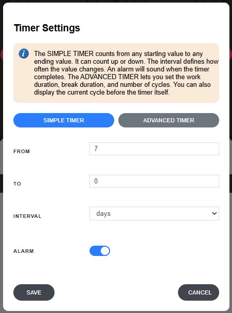
Just as the name implies, Timer Mode is all about keeping track of time—whether you want to count up from zero or count down toward a deadline. I’ve implemented two flavors to suit different needs:
- Basic Timer
- Count up or down at any interval you choose.
- Perfect for tracking how long you’ve been working on a project, timing your coffee break, or counting the days until an event.
- Interval Timer
- Define work and rest periods, plus the number of cycles.
- Originally inspired by interval training, but just as handy for managing focused work sessions and regular breaks, Pomodoro-style.
Both versions include an optional alarm feature. When the timer reaches its end, the flaps start “clapping” in rapid succession—using the display’s natural clicking sound as your built-in buzzer. It’s a tactile, unmistakable way to know your session is up without adding any extra speakers or buzzers.
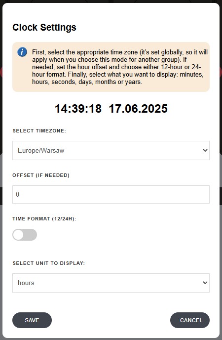
CLOCK
This mode doubles as both a clock and a calendar—just select your time zone, and you’re up and running. You can toggle between 12- and 24-hour formats or apply a manual offset if you need to display a different time.
Under the hood, the main module sports a dedicated RTC chip with battery backup, so even if the power goes out, the display never loses track of time. When juice returns, it immediately syncs back to the correct time without you having to lift a finger.
I also added that little RGB LED for a quick sanity check on your clock’s health:
- Red LED on = display is powered and the clock is running correctly.
- LED off = no power, which means the clock is effectively “paused” until power comes back.
It’s a subtle detail, but having that visual cue means you’ll never wonder whether your calendar or clock has gone out of sync.
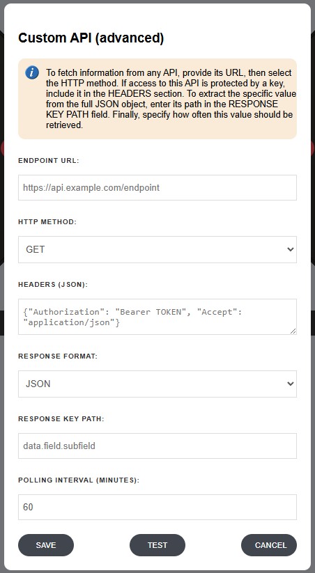
CUSTOM-API
This mode is a bit more advanced—but don’t worry, you’ve got this! 🙂
With API Mode, you’re no longer limited to pre-built functions—you can pull virtually any information from the internet, as long as there’s an API for it.
At its core, an API (Application Programming Interface) is simply a set of rules that lets programs exchange data. Think of it like a waiter at a restaurant: instead of wandering into the kitchen, you place your order (a request) and the waiter brings back exactly what you asked for, neatly plated.
Let’s say you want today’s exchange rate from your bank. With API Mode, your display sends a request to the bank’s API and retrieves just the rate you need—no more manually refreshing a webpage or parsing through tables. Everything happens behind the scenes, so you get a clean, ready-to-use number.
Some APIs are open, meaning you only need the URL to start fetching data. Others are protected by an API key, which usually involves signing up on the provider’s site to obtain credentials. Rest easy: this mode handles both scenarios seamlessly.
Need only a slice of that data? No problem. You can define a filter to extract exactly the field you care about—so if the API returns a giant JSON object, you’ll see only your target value on the flip-display. And before you commit your settings, hit Test in the web app to make sure your filter is pulling the right piece of information.
Conclusion
Building this electromechanical Wi-Fi display has been a rewarding journey that combined disciplines: a bit of mechanical design, a good helping of electronics, and some firmware programming. The result is a unique DIY display that brings a touch of retro engineering to modern data. We explored how H-bridges let us drive currents both ways through coils to flip magnets, how PCB coils can act as compact electromagnets (with some trade-offs against traditional wound coils), and how shift registers allow a microcontroller to control many outputs efficiently. We also delved into the assembly of the device and the thought process behind ensuring the segments move reliably and stay put without continuous power.
I hope this detailed guide serves as a definitive reference for anyone who wants to replicate or build upon this project. Whether you’re displaying your social media stats, building a one-of-a-kind clock, or just exploring the world of electromechanical displays, there’s a lot of fun and learning in making something that clicks and clacks in the physical world.
Feel free to use the provided files and code to make your own, and let me know if you do – I’d love to see more of these displays out there. Happy building, and happy flipping!
Related Articles

SS4H-ZRG Zigbee Rain Gauge – DIY project based Zigbee Door Sensor
In this article, I’m going to show you how to…

SS4H-SSR Smart Extension Board – DIY project based on ESP8266
With these kinds of projects, they are often created when…

SS4H-SHH Smart Home Hub based on ESP32 POE
Personally, I’m a fan of centralized “smart” systems. Thanks to…